Table of Contents
Advertisement
Advertisement
Table of Contents

Summary of Contents for Doseuro Rapida 2.0
- Page 1 ATTENTION: Industrial machinery for professional use. These instructions are for qualified personnel TRANSLATION OF ORIGINAL INSTRUCTIONS User's manual for inverter motor Rapida 2.0 __________________________________________________ Manual Display Version Rapida 2.0...
- Page 2 23/04/2021 Correction Ch.3, tA up to 45°C L. FUMAGALLI 11/05/2021 This manual refers to the following products: Inverter motor “Rapida 2.0 02” Inverter motor “Rapida 2.0 03” Inverter motor “Rapida 2.0 05” Inverter motor “Rapida 2.0 07” 2/24 Ed. 2021...
-
Page 3: Table Of Contents
INSTALLATION AND OPERATING MANUAL DISPLAY VERSION DOCUMENTATION CODE: Dosing machine graphic display panel manual (XMPI0MTIRPD2ST021) EDITION DATE: 04/06/2020 SOFTWARE VERSION: rev.25.1 Table of contents INTRODUCTION ................................4 REMINDER OF SAFETY INSTRUCTIONS ........................4 PRODUCT DESCRIPTION ............................4 GENERAL CHARACTERISTICS ............................. 4 AVAILABLE INPUTS/OUTPUTS ........................... -
Page 4: Introduction
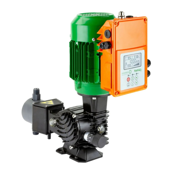
PRODUCT DESCRIPTION The RAPIDA 2.0 inverter motor is an assembly of a three-phase asynchronous electric motor and an inverter board, designed to allow the speed of the motor to be varied. - Page 5 Inverter output: three-phase for asynchronous motors with 230/400V windings (on request from 110V/50 Hz with appropriate power derating). Inverter output frequency: 6 to 60 Hz in standard Rapida 2.0 configuration 0 to 160 Hz nominal inverter. Type of operation: V/F SVM (“Space Vector Modulation”).
-
Page 6: Available Inputs/Outputs
AVAILABLE INPUTS/OUTPUTS The RAPIDA 2.0 series inverter motors have the following I/O resources for control and interfacing: • No. 4 low safety voltage digital inputs with programmable functions. Type of control contacts: o free of potential; o with n. 1 common terminal. -
Page 7: Electrical Installation Of The Inverter Motor In The System
ELECTRICAL INSTALLATION OF THE INVERTER MOTOR IN THE SYSTEM It is essential to read this chapter before proceeding with the electrical installation of the new or replacement inverter or with re-installation following maintenance in the existing system. Installation of the motor-inverter in the system may only be carried out by electrical installers, manufacturers and professional operators in possession of the technical and professional qualifications required by the laws in force. -
Page 8: Inverter Motor Power Supply
Key: 1 Power supply terminal block 10 HSI/Encoder control input connector 2 Power fuse 11 Earth connection faston 3 Motor connection faston 12 Input connector reserved for 4-key keyboard 4 RS485 serial connection terminal 13 Inverter registration label 6 ALS-1 terminal connector and RS485 serial connector 17 Analog input mode selector (Volt/mA) 7 Programmable output connector 18 Hardware version reference... -
Page 9: Connection Of The Analogue Speed Reference
2.4. CONNECTION OF THE ANALOGUE SPEED REFERENCE HARDWARE SETTINGS ON REFERENCE TYPE CONNECTION ON CONNECTOR 9 CONNECTOR 17 0 ÷ 10 V 0 ÷ 5 V A = OFF A = OFF Analogue voltage signal B = OFF B = OFF C = OFF C - D = jumper D = OFF... -
Page 10: Uninstallation And Open Enclosure Operations
UNINSTALLATION AND OPEN ENCLOSURE OPERATIONS After switching off the motor-inverter, the upper cover of the inverter can be opened by unscrewing the four screws. After that, the necessary uninstallation or maintenance operations are possible. WARNING - RISK OF ELECTRIC SHOCK: Do not perform any type of direct operation on internal parts or open the cover of the inverter unless it is powered down. -
Page 11: Graphic Display
GRAPHIC DISPLAY The graphic display panel mounted on the inverter allows the display of parameters and the management of the dosing pump. GRAPHIC DISPLAY PANEL The version of the Rapida with graphic display panel looks like the picture opposite, with the display already FLAT CABLE FOR COMMUNICATION connected to the inverter via the two BETWEEN INVERTER AND DISPLAY... -
Page 12: Display Menu
DISPLAY MENU D001 – HOMEPAGE (FLOW RATE) Motor current IGBT module 50.0 °C temperature % analogue Output value input scale D002 – OUTPUT FREQUENCY Motor current IGBT module 50.0 °C temperature 42.4 % analogue Output value input scale D003 – PERCENTUALE Motor current IGBT module 50.0... - Page 13 D006 - MOTOR CURRENT IGBT module Engine revolutions 49.0 1272 °C temperature per minute 1.76 Arms RMS active Power factor 31.0 0.08 power (cos φ) D007 - INVERTER TEMPERATURE Output Engine revolutions frequency per minute 33.0 °c Motor current Power factor 0.31 0.66 (cos φ)
- Page 14 D009 – OUTPUTS Output Engine revolutions 42.4 1272 frequency per minute Motor current Power factor 1.81 0.08 (cos φ) The layout of the outputs is as shown in the table below. Digit 1 is the one furthest to the right. For output status, 0 = OFF, 1 = ON.
-
Page 15: Setup Menu
If the display is password-protected and unlocked, access to the setup menu will be automatically locked again after one minute of inactivity on the keys. To remove the root password, simply reset parameter D141 to 0000. D150-D151- USER PASSWORD Same principle as D140-D141, with the difference that this password blocks access and modification of the user setup menu. -
Page 16: Detailed Description Of The Main Registers
S014 INPUT CONFIGURATION 4 (8.4) N.O./N.C. N.O. S015 BEHAVIOUR IN CASE OF ERROR ON IN.3 STOP/RESTART RESTART S016 BEHAVIOUR IN CASE OF ERROR ON IN.4 STOP/RESTART RESTART S017 ERROR IN CASE OF SENSOR FAILURE ON/OFF S018 PARAMETER DISPLAYED AT SWITCH-ON 1÷202 S019 MAXIMUM INVERTER MOTOR TEMPERATURE... - Page 17 S009 - ADJUSTMENT OF LINE Q (FLOW RATE) 40÷50 - By modifying this parameter it is possible to change the values of the flow rate as a function of frequency for the range of the Q line from 61%÷80%. S0010 - ADJUSTMENT OF LINE Q (FLOW RATE) 50÷60 - By modifying this parameter it is possible to change the values of the flow rate as a function of frequency for the range of the Q line from 81%÷100%.
-
Page 18: User Setup Menu
9 USER SETUP MENU In this menu it is possible to modify user settings for the correct operation of the system. All these parameters can also be configured via the SETUP MENU (which is protected and set at the factory during testing). Changing one of these parameters will automatically change the equivalent parameter in the factory setup menu and vice versa. -
Page 19: Mode Of Operation
10 MODE OF OPERATION 10.1 AUTOMATIC MODE Valid for menus D001, D002, D003. Entering one of these pages, pressing the RUN button will start the system and use the analogue input to adjust the range or the arrows on the keypad for manual mode when this mode has previously been selected via the MAN button. -
Page 20: Connection Diagrams
11 CONNECTION DIAGRAMS ATTENTION: the version with graphic panel display is supplied with all the necessary connections already made. You only need to read this chapter if you need to reconnect the display to the inverter. 11.1 DISPLAY BOARD LAYOUT IGURE Key: 1 JST power connector... -
Page 21: Connecting The Display To The Inverter
11.2 CONNECTING THE DISPLAY TO THE INVERTER The display must be connected to the inverter via two cables: • The 5x2 flat cable is used for communication between the inverter and the display; • The power cable for the display. 11.2.1 Connecting cables to the display Connect the flat to the display, paying attention to its polarity: the arrow on the cable connector (coinciding with the wire of a different colour) must be aligned with pin 1 marked by the indentation on connector number... -
Page 22: Diagnostics And Troubleshooting
(which must be solved by adding auxiliary ventilation to the motor, otherwise the motor may burn out). Doseuro recommends the application of the servo-ventilated motor for continuous use (over 30 min.) of the pump at a frequency <= 20 Hz. -
Page 23: Displaying Errors And Protections
12.2 DISPLAYING ERRORS AND PROTECTIONS Error codes (stored in parameters D101 to D105) ERROR CODE DISPLAY DESCRIPTION ERR OT Power module overtemperature ERR OL Overcurrent ERR EF "External Fault' (emergency input activation) ERR OV Overvoltage Motor protection for average cosɸ greater than the set value over a time greater than ERR PF 5 times the reference parameter ERR cL... - Page 24 For better use of your dosing pump, choose: DOSEURO S.r.l. ACCESSORIES Contact our Sales Office Via G. Carducci, 141 - 20093 Cologno Monzese (Mi) - Italy Tel. +39 0227301324 - Fax. +39 0226700883 http:// www.doseuro.com e-mail: info@fpz.com...
Need help?
Do you have a question about the Rapida 2.0 and is the answer not in the manual?
Questions and answers