Table of Contents
Advertisement
ProtoNode FPC-N34 and ProtoNode FPC-N35
Start-up Guide
For Interfacing Camus Products:
Sola, DynaFLO, Valiant
To Building Automation Systems:
BACnet MS/TP, BACnet/IP, Metasys N2, Modbus TCP/IP LonWorks and
SMC Cloud
APPLICABILITY & EFFECTIVITY
Explains ProtoNode hardware and how to install it.
The instructions are effective for the above as of December 2020.
Document Revision: 5.A
Web Configurator
Template Revision: 72
Advertisement
Table of Contents

Summary of Contents for Camus Hydronics ProtoNode FPC-N34
- Page 1 ProtoNode FPC-N34 and ProtoNode FPC-N35 Start-up Guide For Interfacing Camus Products: Sola, DynaFLO, Valiant To Building Automation Systems: BACnet MS/TP, BACnet/IP, Metasys N2, Modbus TCP/IP LonWorks and SMC Cloud APPLICABILITY & EFFECTIVITY Explains ProtoNode hardware and how to install it.
- Page 2 Camus ProtoNode Start-up Guide Technical Support Thank you for purchasing the ProtoNode for Camus. Please call Camus for technical support of the ProtoNode product. MSA Safety does not provide direct support. If Camus needs to escalate the concern, they will contact MSA Safety for assistance.
- Page 3 (Section 4.2) 7. If using a serial field protocol: Connect the ProtoNode FPC-N34 3 pin RS-485 port to the field protocol cabling, (Section 4.3) or connect the ProtoNode FPC-N35 2 pin LonWorks port to the field protocol cabling. (Section 4.4) 8.
-
Page 4: Table Of Contents
Connection from DynaMaxHS to ProtoNode ................18 Connection from DynaFLO to ProtoNode ................. 19 Connection from Valiant to ProtoNode ..................21 ProtoNode FPC-N34 and FPC-N35 Showing Connection Ports ..........23 Serial Device Connections to the ProtoNode ................24 4.6.1 Biasing the RS-485 Device Network ..................25 4.6.2... - Page 5 Camus ProtoNode Start-up Guide Appendix A.5.1. Taking a Capture with Older Firmware ..............52 Appendix B. Additional Information ......................54 Update Firmware ......................54 BACnet: Setting Network_Number for More Than One ProtoNode on the Subnet ..54 Securing ProtoNode with Passwords ................55 Internet Browser Software Support ..................
- Page 6 Figure 7: Baud Rate DIP Switches ......................14 Figure 8: BMS Baud Rate ........................... 14 Figure 9: ProtoNode FPC-N34 (Top) and ProtoNode FPC-N35 (Bottom) ..........23 Figure 10: Device and Power Connections....................24 Figure 11: RS-485 Biasing Switch on the ProtoNode N34 (Left) and ProtoNode N35 (Right) ....25 Figure 12: RS-485 End-Of-Line Termination Switch on the ProtoNode N34 (Left) and ......
-
Page 7: Certifications
Camus ProtoNode Start-up Guide CERTIFICATIONS BTL Mark – BACnet Testing Laboratory ® 1 The BTL Mark on ProtoNode is a symbol that indicates that a product has passed a series of rigorous tests conducted by an independent laboratory which verifies that the product correctly implements the BACnet features claimed in the listing. -
Page 8: Introduction
Camus ProtoNode Start-up Guide INTRODUCTION ProtoNode Gateway The ProtoNode is an external, high performance building automation multi-protocol gateway that is preconfigured to communicate between Camus’ products (hereafter called “device”) connected to the ProtoNode and configure them for BACnet MS/TP, BACnet/IP, Metasys N2 by JCI, Modbus TCP/IP or ®2 LonWorks... - Page 9 Camus ProtoNode Start-up Guide FPC-N35 Connectivity Diagram: The ProtoNode can connect with the SMC Cloud. The SMC Cloud allows technicians, the OEM's support team and MSA Safety's support team to remotely connect to the ProtoNode. The SMC Cloud provides the following capabilities for any registered devices in the field: Remotely monitor and control devices.
-
Page 10: Setup For Protonode
Each ProtoNode has a unique part number located on the side or the back of the unit. This number should be recorded, as it may be required for technical support. The numbers are as follows: Model Part Number ProtoNode FPC-N34 FPC-N34-0565 ProtoNode FPC-N35 FPC-N35-0566 Figure 1: ProtoNode Part Numbers •... -
Page 11: Configuring Device Communications
Camus ProtoNode Start-up Guide Configuring Device Communications 3.3.1 Confirm the Device and ProtoNode COM Settings Match Any connected serial device MUST have the same baud rate, data bits, stop bits, and • parity settings as the ProtoNode. • Figure 4 specifies the device serial port settings required to communicate with the ProtoNode. -
Page 12: Selecting The Desired Protocol Configuration
Camus ProtoNode Start-up Guide Selecting the Desired Protocol Configuration • ProtoNode FPC-N34 units use the “S” bank of DIP switches (S0 – S3) to select the protocol configuration. See the table in Figure 5 for the switch settings to select The OFF position is when the DIP switches are set closest to the outside of the box •... -
Page 13: Bms Network Settings: Mac Address, Device Instance And Baud Rate
Camus ProtoNode Start-up Guide BMS Network Settings: MAC Address, Device Instance and Baud Rate 3.5.1 BACnet MS/TP (FPC-N34): Setting the MAC Address for BMS Network Only 1 MAC Address is set for ProtoNode regardless of how many devices are connected to •... -
Page 14: Bacnet (Fpc-N34): Calculating The Default Device Instance
BMS for BACnet MS/TP. • The ProtoNode baud rate for Metasys N2 is set for 9600. DIP switches B0 – B3 are disabled for Metasys N2 on the ProtoNode FPC-N34. DIP switches B0 – B3 are disabled on the ProtoNode FPC-N35 (LonWorks). •... -
Page 15: Interfacing Protonode To Devices
Camus ProtoNode Start-up Guide INTERFACING PROTONODE TO DEVICES 4.1 Connection from DynaFlame/Dynaforce/Advantus/Avenger to ProtoNode The DynaFlame®/Dynaforce® terminals J3-MB2 (+, -) are connected to the Protonode as shown. • Boiler 1: MB1 Modbus Address = MB2 Modbus Address = 1 • Boiler 2: MB2 Modbus Address = MB2 Modbus Address = 2 etc. - Page 16 Camus ProtoNode Start-up Guide Activating Comm. Port 2 on Sola Display > Select Gateway tab 1) Select Gateway tab 2) Check Enable Modbus gateway 3) Select Gateway on COM2 port 1) Select COM2 tab 2) Check Enable COM2 port Page 16 of 87...
- Page 17 Camus ProtoNode Start-up Guide Verify activity on COM2 port > > COM1: Modbus data between Diana and SOLA COM2: Modbus data between Diana and front end (Modbus) or ProtoNode Page 17 of 87...
-
Page 18: Connection From Dynamaxhs To Protonode
Camus ProtoNode Start-up Guide 4.2 Connection from DynaMaxHS to ProtoNode Programming DynaMax Place Local/Modbus toggle switch in LOCAL Press and select Login, enter “sola” Select Advanced Setup Select System Select System ID & Access Verify MB1 Modbus address = 1. To be in sequential order. Verify MB2 Modbus address = 1. -
Page 19: Connection From Dynaflo To Protonode
Camus ProtoNode Start-up Guide 4.3 Connection from DynaFLO to ProtoNode Start-up screen > Setup (password:3232) > Modbus: Assign a network ID or slave address to DynaFLO’s controller by pressing <Network ID #> and inserting a number. Make sure the <Modbus ON> is switched to “Modbus ON”. When <Modbus ON/OFF>... - Page 20 Camus ProtoNode Start-up Guide Use the RJ11 cable connector shown below (provided with your DynaFLO) or a similar RJ11 (6POS2C) cable to connect to Port 2 of your DynaFLO’s PLC. Pin Number Function A signal (+) TX+/RX+ B signal (-) TX-/RX- Having access to pins 1 and 6 of Port2 on DynaFLO by using the RJ11 (6POS2C) cable, make connections to the Protonode according to the above table: Please refer to appendix C.2 for DynaFLO’s Modbus mapping table.
-
Page 21: Connection From Valiant To Protonode
Camus ProtoNode Start-up Guide 4.4 Connection from Valiant to ProtoNode The RS-485 connection is made by connecting wires from the Protonode to the terminal block located under the Valiant’s control panel. The designated BMS terminals are labelled as shown in the image below for ease of identification: Page 21 of 87... - Page 22 Camus ProtoNode Start-up Guide The slave address can be changed from the Valiant’s pushbutton screen. To change the slave address go to Menu>Settings>General Settings>Other Settings>Modbus Address Note: Do not change “Modbus Stopbits”! Please refer to appendix C.3 for Valiant’s Modbus mapping table. Page 22 of 87...
-
Page 23: Protonode Fpc-N34 And Fpc-N35 Showing Connection Ports
Camus ProtoNode Start-up Guide ProtoNode FPC-N34 and FPC-N35 Showing Connection Ports Figure 9: ProtoNode FPC-N34 (Top) and ProtoNode FPC-N35 (Bottom) Page 23 of 87... -
Page 24: Serial Device Connections To The Protonode
Camus ProtoNode Start-up Guide Serial Device Connections to the ProtoNode ProtoNode 6 Pin Phoenix connector: The 6 pin Phoenix connector is the same for ProtoNode FPC-N34 and FPC-N35 (LonWorks). • Pins 1 through 3 are for RS-485 devices. • Use standard grounding principles for RS-485 GND •... -
Page 25: Biasing The Rs-485 Device Network
Camus ProtoNode Start-up Guide 4.6.1 Biasing the RS-485 Device Network An RS-485 network with more than one device needs to have biasing to ensure proper • communication. The biasing only needs to be done on one device. The ProtoNode has 510 ohm resistors that can be used to set the biasing. The ProtoNode’s default •... -
Page 26: End Of Line Termination Switch For The Rs-485 Device Network
Camus ProtoNode Start-up Guide 4.6.2 End of Line Termination Switch for the RS-485 Device Network On long RS-485 cabling runs, the RS-485 trunk must be properly terminated at each end. • • The ProtoNode has an end of line (EOL) blue jumper. The default setting for this blue EOL switch is OFF with the jumper straddling the pins closest to the inside of the board of the ProtoNode. -
Page 27: Serial Network (Fpc-N34): Wiring Field Port To Rs-485 Network
Camus ProtoNode Start-up Guide Serial Network (FPC-N34): Wiring Field Port to RS-485 Network • Connect the RS-485 network wires to the 3-pin RS-485 connector on ProtoNode as shown below Figure Use standard grounding principles for RS-485 GND See Section for information on connecting to an Ethernet network. •... -
Page 28: Lonworks (Fpc-N35): Wiring Lonworks Devices To The Lonworks Terminal
Camus ProtoNode Start-up Guide LonWorks (FPC-N35): Wiring LonWorks Devices to the LonWorks Terminal • Wire the LonWorks device network to the ProtoNode LonWorks Terminal. Use approved cable per the FT-10 installation guidelines LonWorks has no polarity. Figure 15: LonWorks Terminal Page 28 of 87... -
Page 29: Power-Up Protonode
Camus ProtoNode Start-up Guide Power-Up ProtoNode Check power requirements in the table below: Power Requirement for ProtoNode External Gateway Current Draw Type ProtoNode Family 12VDC/AC 24VDC/AC 30VDC FPC – N34 (Typical) 170mA 100mA 80mA FPC – N34 (Maximum) 240mA 140mA 100mA FPC –... -
Page 30: Use The Protonode Web Configurator To Setup The Gateway
Camus ProtoNode Start-up Guide USE THE PROTONODE WEB CONFIGURATOR TO SETUP THE GATEWAY Connect the PC to the ProtoNode via the Ethernet Port Connect a Cat-5 Ethernet cable (straight through or cross-over) between the local PC and ProtoNode. Ethernet Port Figure 18: Ethernet Port Location 5.1.1 Changing the Subnet of the Connected PC The default IP Address for the ProtoNode is 192.168.1.24, Subnet Mask is 255.255.255.0. -
Page 31: Connecting To The Protonode Web Configurator
Camus ProtoNode Start-up Guide Connecting to the ProtoNode Web Configurator After setting a local PC on the same subnet as the ProtoNode (Section 5.1), open a web browser on the PC and enter the IP Address of the ProtoNode; the default address is 192.168.1.24. NOTE: If the IP Address of the ProtoNode was changed, the assigned IP Address can be discovered using the FS Toolbox utility. -
Page 32: Figure 19: Web Configurator Showing No Active Profiles
Camus ProtoNode Start-up Guide Figure 19: Web Configurator Showing no Active Profiles Page 32 of 87... -
Page 33: Verify Device Communications
Camus ProtoNode Start-up Guide To add an active profile to support a device, click the Add button under the Active Profiles heading. • Select a profile from the drop-down menu field that appears underneath the Current profile column. NOTE: If multiple devices are connected to the ProtoNode, set the BACnet Virtual Server Nodes field to “Yes”;... -
Page 34: Ethernet Network: Setting Ip Address For The Field Network
Camus ProtoNode Start-up Guide Ethernet Network: Setting IP Address for the Field Network Follow the steps outlined in Section • to access the ProtoNode Web Configurator. To access the FS-GUI, click on the “Diagnostics & Debugging” button in the bottom right corner of •... -
Page 35: Figure 23: Changing Ip Address Via Fs-Gui
Camus ProtoNode Start-up Guide From the FS-GUI landing page, click on “Setup” to expand the navigation tree and then select • “Network Settings” to access the IP Settings menu. (Figure Figure 23: Changing IP Address via FS-GUI Modify the IP Address (N1 IP Address field) of the ProtoNode Ethernet port. •... -
Page 36: Bacnet: Setting Node_Offset To Assign Specific Device Instances
Camus ProtoNode Start-up Guide BACnet: Setting Node_Offset to Assign Specific Device Instances Follow the steps outlined in Section • to access the ProtoNode Web Configurator. Node_Offset field shows the current value (default = 50,000). • The values allowed for a BACnet Device Instance can range from 1 to 4,194,303 To assign a specific Device Instance (or range);... -
Page 37: How To Start The Installation Over: Clearing Profiles
Camus ProtoNode Start-up Guide How to Start the Installation Over: Clearing Profiles Follow the steps outlined in Section • to access the ProtoNode Web Configurator. At the bottom-left of the page, click the “Clear Profiles and Restart” button. • Once restart is complete, all past profiles discovered and/or added via Web configurator are •... -
Page 38: Lonworks (Fpc-N35): Commissioning Protonode On A Lonworks Network
Camus ProtoNode Start-up Guide LONWORKS (FPC-N35): COMMISSIONING PROTONODE ON A LONWORKS NETWORK Commissioning may only be performed by the LonWorks administrator. Commissioning ProtoNode FPC-N35 on a LonWorks Network During the commissioning process, the LonWorks administrator may prompt the user to hit the service pin on the ProtoNode FPC-N35 at a specific point (this step occurs at different points of the commissioning process for each LonWorks network management tool). -
Page 39: Figure 27: Sample Of Fserver.xif File Generated
Camus ProtoNode Start-up Guide Click the Okay button to close the Internet Protocol window and the Close button to close the • Ethernet Properties window. Open a web browser and go to the following address: [IP Address of ProtoNode]/fserver.xif • Example: 192.168.1.24/fserver.xif If the web browser prompts to save the file, save the file onto the PC. -
Page 40: Using The Embedded Bacnet Explorer
Camus ProtoNode Start-up Guide USING THE EMBEDDED BACNET EXPLORER The embedded BACnet Explorer allows installers of the OEM product to validate that their equipment is working on BACnet without having to ask the BMS integrator to test the unit. To access the embedded BACnet Explorer, go to the FS-GUI page and click the Explorer button. •... -
Page 41: Discover Device List
Camus ProtoNode Start-up Guide NOTE: For BACnet/IP, click on the Settings button on the left side of the landing page to ensure the ProtoNode is on the BACnet/IP network subnet or to configure BBMD. Discover Device List From the BACnet Explorer landing page, click on the BACnet Explorer button on the left side of the •... -
Page 42: View Device Details And Explore Points/Parameters
Camus ProtoNode Start-up Guide NOTE: The “Discover All Devices” or “Discover All Networks” checkboxes must be unchecked to search for a specific device range or network. NOTE: Allow the devices to populate before interacting with the device list for optimal performance. -
Page 43: Figure 34: Full Device Sub-Items
Camus ProtoNode Start-up Guide To view the full details of a device, highlighting the device directly (in Figure 34 “1991 • WeatherLink_1”) and click the Explore button ( ) that appears to the right of the highlighted device as a magnifying glass icon or double-click the highlighted device. Figure 34: Full Device Sub-items Now additional device details are viewable;... -
Page 44: Figure 36: Additional Device Details
Camus ProtoNode Start-up Guide Then click on the Explore button or double-click the device object. • Figure 36: Additional Device Details A full list of the device details will appear on the right side window. If changes are expected since the last explore, simply press the Refresh button ( ) that appears to right of individual properties to refresh the value. -
Page 45: Edit The Present Value Field
Camus ProtoNode Start-up Guide 7.2.1 Edit the Present Value Field The only recommended field to edit via BACnet Explorer is the device’s present value field. NOTE: Other BACnet properties are editable (such as object name, object description, etc.); however, this is not recommended because the BACnet Explorer is a discovery tool not a Building Management System (BMS). -
Page 46: Figure 39: Updated Present Value
Camus ProtoNode Start-up Guide Enter the appropriate change and click the Write button. • The window will close. When the BACnet Explorer page appears, the present value will be changed as specified. Figure 39: Updated Present Value Page 46 of 87... -
Page 47: Appendix A. Troubleshooting
Camus ProtoNode Start-up Guide Appendix A. Troubleshooting Lost or Incorrect IP Address • Ensure that FieldServer Toolbox is loaded onto the local PC. Otherwise, download the FieldServer-Toolbox.zip via the Sierra Monitor website’s Software Downloads. Extract the executable file and complete the installation. •... -
Page 48: Viewing Diagnostic Information
Camus ProtoNode Start-up Guide Viewing Diagnostic Information • Type the IP Address of the ProtoNode into the web browser or use the FieldServer Toolbox to connect to the ProtoNode. Click on Diagnostics and Debugging Button, then click on view, and then on connections. •... -
Page 49: Check Wiring And Settings
Camus ProtoNode Start-up Guide Check Wiring and Settings • No COMS on Modbus RTU side. If the Tx/Rx LEDs are not flashing rapidly then there is a COM issue. To fix this, check the following: Visual observations of LEDs on the ProtoNode (Appendix A.4) Check baud rate, parity, data bits, stop bits... -
Page 50: Led Diagnostics For Communications Between Protonode And Devices
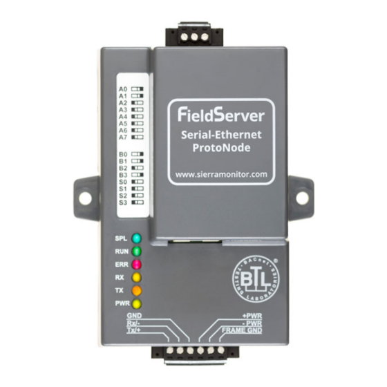
Camus ProtoNode Start-up Guide LED Diagnostics for Communications Between ProtoNode and Devices See the diagram below for ProtoNode FPC-N34 and FPC-N35 LED Locations. Diagnostic LEDs Description The SPL LED will light if the unit is not getting a response from one or more of the configured devices. -
Page 51: Take A Fieldserver Diagnostic Capture
Camus ProtoNode Start-up Guide Take a FieldServer Diagnostic Capture When there is a problem on-site that cannot easily be resolved, perform a Diagnostic Capture before contacting support. Once the Diagnostic Capture is complete, email it to technical support. The Diagnostic Capture will accelerate diagnosis of the problem. If the FieldServer bios is updated/released on November 2017 or later then the Diagnostic Capture is performed via the gateway’s on-board system. -
Page 52: Appendix A.5.1. Taking A Capture With Older Firmware
Camus ProtoNode Start-up Guide Send the diagnostic zip file to technical support. • NOTE: Diagnostic captures of BACnet MS/TP communication are output in a “.PCAP” file extension which is compatible with Wireshark. Appendix A.5.1. Taking a Capture with Older Firmware If the FieldServer firmware is from before November 2017, the Diagnostic Capture can be done by downloading the FieldServer Toolbox software but network connections (such as Ethernet and Wi-Fi) cannot be captured (if a network diagnostic is needed take a Wire Shark capture). - Page 53 Camus ProtoNode Start-up Guide Select “Full Diagnostic" from the drop down menu NOTE: If desired, the default capture period can be changed. Click on the Start Diagnostic button Wait for the capture period to finish and the Diagnostic Test Complete window will appear Step 2: Send Log •...
-
Page 54: Appendix B. Additional Information
Camus ProtoNode Start-up Guide Appendix B. Additional Information Update Firmware To load a new version of the firmware, follow these instructions: 1. Extract and save the new file onto the local PC. 2. Open a web browser and type the IP Address of the FieldServer in the address bar. Default IP Address is 192.168.1.24 Use the FS Toolbox utility if the IP Address is unknown (Appendix... -
Page 55: Securing Protonode With Passwords
Camus ProtoNode Start-up Guide Securing ProtoNode with Passwords Access to the ProtoNode can be restricted by enabling a password on the FS-GUI Passwords page – click Setup and then Passwords in the navigation panel. There are 2 access levels defined by 2 account names: Admin and User. -
Page 56: Internet Browser Software Support
Camus ProtoNode Start-up Guide Internet Browser Software Support The following web browsers are supported: • Chrome Rev. 57 and higher Firefox Rev. 35 and higher • Microsoft Edge Rev. 41 and higher • Safari Rev. 3 and higher • NOTE: Internet Explorer is no longer supported as recommended by Microsoft. NOTE: Computer and network firewalls must be opened for Port 80 to allow FieldServer GUI to function. -
Page 57: Appendix C. Vendor Information - Camus
Page 57 of 87 Camus ProtoNode Startup Camus ProtoNode Startup G id G id Appendix C. Vendor Information – Camus NOTE: All Modbus TCP/IP registers are the same as the Modbus RTU registers for the serial device. The Modbus TCP/IP node address of the device is also the same as the Modbus RTU node address. - Page 58 Page 58 of 87 Camus ProtoNode Startup Camus ProtoNode Startup G id G id Active LL setpoint 0012 0018 nvoXActiveLLSP SNVT_temp_p 40 – 200 Burner control status 0020 0032 nvoXBrnCtrlStatus SNVT_count_f 0 = Disabled 1 = Locked Out 2-3 = Reserved 4 = Anti-short cycle 5 = Unconfigured safety data 6-33 = Reserved...
- Page 59 Page 59 of 87 Camus ProtoNode Startup Camus ProtoNode Startup G id G id Outdoor temperature 00AA 0170 nvoXOutdoorTmp SNVT_temp_p 40 – 200 Burner switch 00CB 0203 nvi/nvoXBrnSwitch SNVT_count_f Used to enable/disable burner control. 0 = Off 1 = On NOTE: Writing to this point will result in an alert appearing on screen CH enable...
- Page 60 Page 60 of 87 Camus ProtoNode Startup Camus ProtoNode Startup G id G id All temperature registers are expressed in C regardless of what temperature units are set to on the boiler, ex. 32.0 C = 320. A temperature that is NOT applicable has a value of 0x8FFF.
-
Page 61: Dynaflo Modbus Rtu Mappings To Bacnet, Metasys N2, Modbus Tcp/Ip & Lonworks
Camus ProtoNode Startup Camus ProtoNode Startup G id G id Page 61 of 87 DynaFLO Modbus RTU Mappings to BACnet, Metasys N2, Modbus TCP/IP & LonWorks BACnet Modbus Modbus BACnet Object Point Name Address Register Object ID / N2 Data Lon Name Lon SNVT Note... -
Page 62: Valiant Modbus Rtu Mappings To Bacnet, Metasys N2, Modbus Tcp/Ip & Lonworks
Page 62 of 87 Valiant Modbus RTU Mappings to BACnet, Metasys N2, Modbus TCP/IP & LonWorks BACnet BACnet Object N2 Data Modbus Register Point Name Object LonWorks Name LonWorks SNVT Notes ID/ N2 Type (dec) Type Address Outdoor_temp nvoOutdrTmp_XXX SNVT_temp_p BM_TotalSystemSetpoint nvoBMTotSySP_XXX SNVT_temp_p... - Page 63 Page 63 of 87 BM_Boiler_5_ReqService 20201 nvoBM5ReqSr_XXX SNVT_count_f In Cascade mode only BM_Boiler_6_ReqService 20202 nvoBM6ReqSr_XXX SNVT_count_f In Cascade mode only BM_Boiler_7_ReqService 20203 nvoBM7ReqSr_XXX SNVT_count_f In Cascade mode only BM_Boiler_8_ReqService 20204 nvoBM8ReqSr_XXX SNVT_count_f In Cascade mode only BM_ResetCurveBoilerDesign 21001 nvoBMRsCvBDs_XXX SNVT_temp_p BM_ResetCurveBoilerMildWeather 21002 nvoBMRsCvBWt_XXX...
- Page 64 Page 64 of 87 BM_OverdueCounter14 33020 nvoBMOvrCt14_XXX SNVT_time_hour BM_ServiceInterval 33043 nvoBMSrvInt_XXX SNVT_time_hour Error_0 34008 nvoError0_XXX SNVT_time_hour Error_0_ID 34009 nvoError0ID_XXX SNVT_time_hour Error_0_DoW 34010 nvoError0DoW_XXX SNVT_count_f Error_0_DoM 34011 nvoError0DoM_XXX SNVT_count_f Error_0_M 34012 nvoError0M_XXX SNVT_count_f Error_0_Y 34013 nvoError0Y_XXX SNVT_count_f Error_0_HH 34014 nvoError0HH_XXX SNVT_time_hour Error_0_MM 34015 nvoError0MM_XXX...
- Page 65 Page 65 of 87 0: Initializing 1: Reset 2: Standby 3: Pre-purge 0 4: Pre-purge 1 5: Pre-ignit 6: Ignit 7: Flame proving 8: Burn 9: Post-burn 10: Post-purge 0 11: Post-purge 1 12: Error check 13: Alarm 14: Burner boot Please check the Valiant manual for more detailed information on each state.
- Page 66 Page 66 of 87 BM_Unit_13_GenPumpStatus 40207 nvoU13GnPmSt_XXX SNVT_count_f In Cascade mode only BM_Unit_13_ChFlowRate 40210 nvoU13ChFlRt_XXX SNVT_count_f In Cascade mode only BM_Unit_13_ActualFanSpeed 40212 nvoU13AcFnSp_XXX SNVT_count_f In Cascade mode only BM_Unit_13_SupplySensor 40231 nvoU13SupSen_XXX SNVT_temp_p In Cascade mode only BM_Unit_13_ReturnSensor 40233 nvoU13RetSen_XXX SNVT_temp_p In Cascade mode only BM_Unit_13_FlueSensor 40236...
- Page 67 Page 67 of 87 BM_Unit_17_ChFlowRate 40610 nvoU17ChFlRt_XXX SNVT_count_f In Cascade mode only BM_Unit_17_ActualFanSpeed 40612 nvoU17AcFnSp_XXX SNVT_count_f In Cascade mode only BM_Unit_17_SupplySensor 40631 nvoU17SupSen_XXX SNVT_temp_p In Cascade mode only BM_Unit_17_ReturnSensor 40633 nvoU17RetSen_XXX SNVT_temp_p In Cascade mode only BM_Unit_17_FlueSensor 40636 nvoU17FlSen_XXX SNVT_temp_p In Cascade mode only BM_Unit_17_TotBurnHours 40653...
-
Page 68: Appendix D. Lockout & Alert Codes (Sola)
Page 68 of 87 Appendix D. Lockout & Alert Codes (Sola) Lockout Codes (Sola) Code Description Note None lockout/hold Unconfigured safety data Lockout Waiting for safety data verification Lockout Internal fault: Hardware fault Hold Internal fault: Safety relay feedback error Hold Internal fault: Unstable power (DCDC) output Hold... - Page 69 Page 69 of 87 Internal fault: Safety key 9 Lockout Internal fault: Safety key 10 Lockout Internal fault: Safety key 11 Lockout Internal fault: Safety key 12 Lockout Internal fault: Safety key 13 Lockout Internal fault: Safety key 14 Lockout Flame rod to ground leakage Hold Static flame (not flickering)
- Page 70 Page 70 of 87 Pilot test flame timeout Lockout Flame circuit timeout Lockout 114-121 RESERVED Lightoff rate proving failed Lockout Purge rate proving failed Lockout High fire switch OFF Hold High fire switch stuck ON Hold Low fire switch OFF Hold Low fire switch stuck ON Hold...
- Page 71 Page 71 of 87 Invalid igniter on during setting Lockout Invalid ignite failure delay setting Lockout Invalid ignite failure response setting Lockout Invalid ignite failure retries setting Lockout Invalid ignition source setting Lockout Invalid interlock open response setting Lockout Invalid Interlock start check setting Lockout Invalid LCI enable setting Lockout...
-
Page 72: Alert Codes (Sola)
Page 72 of 87 Alert Codes (Sola) Code Description None (No alert) Alert PCB was restored from factory defaults Safety configuration parameters were restored from factory defaults Configuration parameters were restored from factory defaults Invalid Factory Invisibility PCB was detected Invalid Factory Range PCB was detected Invalid range PCB record has been dropped EEPROM lockout history was initialized... - Page 73 Page 73 of 87 Illegal Modbus write was attempted Modbus write attempt was rejected (NOT ALLOWED) Illegal Modbus read was attempted Safety processor brown-out reset occurred Application processor watchdog reset occurred Application processor brown-out reset occurred Safety processor watchdog reset occurred Alarm was reset by the user at the control Burner control firing rate was >...
- Page 74 Page 74 of 87 Slow start enabled, but forced rate was invalid Analog output hysteresis was invalid Analog modulation output type was invalid IAS open rate differential was invalid IAS open step rate was invalid Mix max modulation rate was invalid, % vs. RPM Mix max modulation rate was >...
- Page 75 Page 75 of 87 DHW OFF hysteresis was invalid DHW ON hysteresis was invalid DHW hysteresis step time was invalid DHW sensor type was invalid Inlet sensor type was invalid for DHW Outlet sensor type was invalid for DHW DHW storage OFF hysteresis was invalid DHW storage ON hysteresis was invalid DHW modulation sensor type was invalid DHW modulation sensor was not compatible for Auto mode...
- Page 76 Page 76 of 87 No Lead Lag active service was set due to demand priority conflicts No Lead Lag add stage method was specified No Lead Lag drop stage method was specified Using backup Lead Lag header sensor due to sensor failure Lead Lag frost protection rate was invalid Lead Lag drop stage method setting was invalid CH frost protection temperature was invalid...
- Page 77 Page 77 of 87 Abnormal Recycle: Safety relay drive test failed Abnormal Recycle: Demand off during Pilot Flame Establishing Period Abnormal Recycle: LCI off during Drive to Purge Rate Abnormal Recycle: LCI off during Measured Purge Time Abnormal Recycle: LCI off during Drive to Lightoff Rate Abnormal Recycle: LCI off during Pre-Ignition test Abnormal Recycle: LCI off during Pre-Ignition time Abnormal Recycle: LCI off during Main Flame Establishing Period...
- Page 78 Page 78 of 87 Abnormal Recycle: Hardware flame rod short Abnormal Recycle: Hardware invalid power Abnormal Recycle: Hardware invalid AC line Abnormal Recycle: Hardware SLO flame ripple Abnormal Recycle: Hardware SLO flame sample Abnormal Recycle: Hardware SLO flame bias range Abnormal Recycle: Hardware SLO flame bias heat Abnormal Recycle: Hardware SLO spark stuck Abnormal Recycle: Hardware SLO spark changed...
- Page 79 Page 79 of 87 Abnormal Recycle: Fan Speed Range High 383-450 RESERVED Circulator control was invalid Circulator P-gain was invalid Circulator I-gain was invalid Circulator temperature was invalid Circulator outlet temperature was invalid Circulator inlet temperature was invalid Circulator outdoor temperature was invalid Circulator sensor choice was invalid Circulator PID setpoint was invalid LCI lost in run...
- Page 80 Page 80 of 87 Mix outdoor temperature was invalid Mix ODR time of day setpoint was invalid Mix ODR time of day setpoint exceeds normal setpoint Mix ODR max outdoor temperature was invalid Mix ODR min outdoor temperature was invalid Mix ODR low water temperature was invalid Mix ODR outdoor temperature range was invalid Mix ODR water temperature range was invalid...
- Page 81 Page 81 of 87 Camus ProtoNode Startup G id Heat exchanger T-rise wasn't allowed due to stack limit setting Heat exchanger T-rise wasn't allowed due to stack connector setting Outlet T-rise wasn't allowed due to outlet connector setting T-rise delay was not configured for recycle response Heat exchanger high limit setpoint was out of range Heat exchanger high limit response was invalid Heat exchanger high limit was exceeded...
-
Page 82: Pump Status Codes (Sola)
Page 82 of 87 Camus ProtoNode Startup G id Pump Status Codes (Sola) Status Description Note Forced On from manual pump control Forced On due to Outlet high limit is active Forced On from burner demand Forced On due to Lead Lag slave has demand Forced Off from local DHW priority service Forced Off from Lead Lag DHW priority service Forced Off from Central Heat anti-condensation... -
Page 83: Appendix E. Mac Address Dip Switch Settings
Page 83 of 87 Camus ProtoNode Startup G id Appendix E. MAC Address DIP Switch Settings MAC Address DIP Switch Settings Address Address ProtoCessor 1991 Tarob Court Milpitas, California 95035 USA Web: www.protocessor.com Tel: (408) 964-4444 Fax: (408) 964-4425 email: support@protocessor.com... - Page 84 Page 84 of 87 Camus ProtoNode Startup G id Address Address ProtoCessor 1991 Tarob Court Milpitas, California 95035 USA Web: www.protocessor.com Tel: (408) 964-4444 Fax: (408) 964-4425 email: support@protocessor.com...
- Page 85 Page 85 of 87 Camus ProtoNode Startup G id Address Address ProtoCessor 1991 Tarob Court Milpitas, California 95035 USA Web: www.protocessor.com Tel: (408) 964-4444 Fax: (408) 964-4425 email: support@protocessor.com...
-
Page 86: Appendix F. Reference
Page 86 of 87 Camus ProtoNode Startup G id Appendix F. Reference Specifications ProtoNode FPC-N34 ProtoNode FPC-N35 One 6-pin Phoenix connector with: One 6-pin Phoenix connector with: RS-485 port (+ / - / gnd) RS-485 port (+ / - / gnd) -
Page 87: Appendix G. Limited 2 Year Warranty
Page 87 of 87 Camus ProtoNode Startup G id Appendix G. Limited 2 Year Warranty MSA Safety warrants its products to be free from defects in workmanship or material under normal use and service for two years after date of shipment. MSA Safety will repair or replace any equipment found to be defective during the warranty period.
Need help?
Do you have a question about the ProtoNode FPC-N34 and is the answer not in the manual?
Questions and answers