
Related Manuals for AVE AF927PLUS

Summary of Contents for AVE AF927PLUS
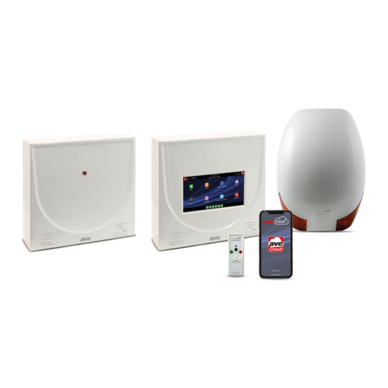
- Page 1 AF927PLUS and AF927PLUSTC Wireless/Wired central units with built-in Wi-Fi module INSTALLATION AND USER MANUAL INSTALLER & USER MANUAL FOR CENTRAL UNITS AF927PLUS – AF927PLUSTC...
-
Page 2: Table Of Contents
PRELIMINARY OPERATIONS ..............................9 PRELIMINARY OPERATIONS FOR CONNECTION TO AVECLOUD (RECOMMENDED)............. 9 DEFAULT DATA AND QUICK PROGRAMMING FOR AF927PLUS (model without screen) ........... 10 RAPID PROGRAMMING FOR AF927PLUSTC (model with screen) ..................25 CONTROL UNIT MENU - INSTALLER INSTRUCTIONS ........................ 28 SUMMARY OF HOME PAGE FUNCTIONS .......................... -
Page 3: Af927Plus And Af927Plustc - Installation Manual
AF927PLUS and AF927PLUSTC - INSTALLATION MANUAL INTRODUCTION AF927PLUS is a wireless / wired central unit with built-in Wi-Fi module. It can manage up to 99 detectors individually identifiable through the "label" function which, when properly programmed, shows the point of origin of the alarm on the display (eg: living room, kitchen, corridor, etc.). -
Page 4: Technical Features
TECHNICAL FEATURES Note: the following is valid for both AF927PLUS and AF927PLUSTC models, unless otherwise specified. The difference between the two central units is only relative to the presence of a 7” LCD screen on the AF927PLUSTC central unit which has been replaced by a LED on the AF927PLUS central unit. -
Page 5: Power Supply Unit
SIM credit EC Declaration of Conformity: The manufacturer AVE SPA declares that the radio-based intrusion detection control unit, code AF927PLUSTC and AF927PLUS and related GSM module AFGSM04, comply with Directive 2014/53/EU. The full text of the EU declaration of conformity is available at: www.ave.it. -
Page 6: Sizing Of The System
Limit for current designated to supply wired peripherals, achieved with resettable polyswitch: this must not exceed 200mA if the control unit has 2 batteries, 80mA if it has only one battery. DISPLAY ELEMENTS • AF927PLUS: multifunction LED. Green, on steady = control unit off... -
Page 7: Installation
SMS messages, digital calls to surveillance centres. All operating functions can be managed remotely via smartphone, tablet, web page and through the free AVE Cloud application (from activation/deactivation to requesting of control frames and “push” signalling of new events). -
Page 8: Guard Preventing Opening And Removal
Screw Screw Screw Screw GUARD PREVENTING OPENING AND REMOVAL The opening signal is guaranteed by spring-loaded buttons, the removal prevention signal by a magnet that must be secured to the wall/support that will hold the control unit using a special template. CONNECTION TO THE 230Vac POWER SUPPLY Carefully follow the precautions given below: Use flexible cable with conductor having a cross-section of at least 0.75mm... -
Page 9: Programming: Preliminary Operations And Quick Start-Up
Note: to connect the system to the “AVE Cloud” remoting system, the control unit must be connected to the home Wi-Fi network and it must have an Internet connection. Without an Internet connection, the control unit cannot be... -
Page 10: Default Data And Quick Programming For Af927Plus (Model Without Screen)
DEFAULT DATA AND QUICK PROGRAMMING FOR AF927PLUS (model without screen) Note: for version AF927PLUSTC with screen, skip to page 26. The control unit has a Wi-Fi module that can be accessed from any device with a WEB browser. The main data... - Page 11 e) Press the “START” screen to call up the programming WIZARD: the column on the left is used to scroll through the various system programming menus. Pressing any one of them (e.g.: language/country) causes the box to turn grey and the page used to set the parameters of each function appears in the box on the right.
- Page 12 The meanings of the various parameters are given below: ▪ Total activation (cannot be edited by the Power User): enables activation of all system areas; ▪ Total deactivation (cannot be edited by the Power User): enables deactivation of all system areas;...
- Page 13 1. Set Installer Code The installer identification code must be entered as follows: a) Enter: ▪ Name: name of the installer; ▪ CURRENT PIN: 5 or 6-digit installer code; Note: the installer PIN cannot be the same as the user PIN and cannot be “000000”; ▪...
- Page 14 This operation is required to identify the system and to distinguish it from other systems if the same supervision account (via AVE CLOUD and related APP) is used for several systems. b. Confirm by pressing OK. 3. Set Name of the various areas used to group together the detectors installed on the system: a.
- Page 15 (HTTP snapshot) - For compatibility and other info, log onto https://www.ispyconnect.com/sources.aspx and/or see the list of products tested by the AVE INTEAM service. c. If you wish to acquire a new intrusion detection device (detectors, remote controls, sirens), click on “Add devices via radio”, the control unit enters listening mode while awaiting the association request message...
- Page 16 To acquire peripheral devices, proceed as follows: Actions to be completed for Code Description Acquisition mode acquisition AF943R Remote control Press RED+GREEN Enter name and configure keys AF915R-DB AD915R-MDB AF963R-DB Detectors Insert battery Enter name, match areas AF964R-DB AF965R-DB AF976R-DB AF53903R-DB Siren Insert battery...
- Page 17 d. To acquire a new intrusion detection device connected to the wired bus generated by the AF927INTFIL interface board, click on “Addַ wiredַ BUSַ devices”; this calls following screen: To enable the control unit to associate the input/output boards connected to the wired bus, just select the manual or automatic device association procedure.
- Page 18 5. Voice messages: The control unit has voice messages for differentiated, type-specific alerts: EVENTS, AREAS, SYSTEM, DEVICES. The control unit software contains pre-recorded messages for the main system events: • EVENTS: Alarm = “Intrusion Alarm” Tamper = “Tampering in progress” Battery dead = “Battery dead”...
- Page 19 If, for example, you wish to change the alarm message: a. Click on the “Events” icon to call up the following screen: b. Edit the necessary voice messages: • The speaker icon has two states: voice message recorded voice message not recorded •...
- Page 20 Internet connection. Specify the e-mail parameters for the account that will be used as control unit sender Set the parameters for connection to AVE CLOUD Set the advanced communication functions, including digital surveillance protocols (ADM, SIA, etc.)
- Page 21 a. Wi-Fi parameters It is possible to define different control unit operating modes: • Wi-Fi ACCESS POINT CONNECTION PARAMETERS • Wi-Fi CLIENT CONNECTION PARAMETERS • LAN CONNECTION PARAMETERS • WI-FI DISABLED (the Wi-Fi module can only be switched off for control units with LCD screen art. AF927PLUSTC) Activating the selected mode calls up a screen used to set the network parameters.
- Page 22 Example of Wi-Fi configuration in CLIENT mode The meaning of the main network parameters to be set are given below: • CONTROL UNIT IP: IP address assigned to the control unit; • SUBNETMASK: defines the size (understood as address range) of the IP subnetwork. Typically, in a home network, the parameter is set to 255.255.255.0;...
- Page 23 Exampled of a Wired LAN configuration The control unit can be connected to the wired LAN using the interface AF927INTFIL (optional). To connect the interface, the cover of the control unit needs to be opened; the interface must be connected in the mini USB port located on the left side of the control unit.
- Page 24 Continue by reconnecting to the control unit using the settings entered Proceed with programming b. Cloud: to connect the control unit to the “AVE CLOUD” remoting system, in the control unit parameters, enter the codes received by e-mail when the system was registered on the https://avecloud.ave.it/...
-
Page 25: Rapid Programming For Af927Plustc (Model With Screen)
RAPID PROGRAMMING FOR AF927PLUSTC (model with screen) When the control unit is switched on for the first time, the following screen appears: Quick programming from a PC and/or other device equipped with a browser cannot be performed at initial start-up, and without entering the user and installer codes. - Page 26 b. Click on the POWER USER (MASTER USER) symbol. This calls up a screen used to set the PIN (6 digits) and other user parameters: c. Confirm by pressing OK. d. Exit the programming wizard (by pressing the home button e.
- Page 27 From any browser click “Settings” on the home page and enter the code for the Power User (Master User) Press “installer settings” and enter the installer code: This calls up the first of the following screens; from here select “General settings” and then “Programming summary”.
-
Page 28: Control Unit Menu - Installer Instructions
CONTROL UNIT MENU - INSTALLER INSTRUCTIONS SUMMARY OF HOME PAGE FUNCTIONS The main screen (home page) summarises control unit status Settings menu button GSM signal level Home page button System name Wi-Fi signal level Connected user type icon Cloud status and cloud Back-up battery charge level menu Remote assistance... -
Page 29: Meaning Of Multi-Status Icons
MEANING OF MULTI-STATUS ICONS Type of user connected to the control unit: Note: indication of the type of user connected can only be activated from the WEB BROWSER and only if the “ENABLE IMMEDIATE INFORMATION” function is active. No user connected POWER USER connected USER connected INSTALLER connected... -
Page 30: Meaning Of The Other Control Unit Icons
MEANING OF THE OTHER CONTROL UNIT ICONS System activation See user manual - Function not permitted for installer. Control Unit Events Memory See settings menu - the installer can only access this by first calling up the settings menu. Scenarios Management and Time Programmer See settings menu - the installer code can access this via the settings menu –... - Page 31 2. Enter the Power User code and press the “Installer Settings” icon; 3. enter the installer code and press “OK” 4. This calls up the menus with the settings enabled for the installer: INSTALLER & USER MANUAL FOR CENTRAL UNITS AF927PLUS – AF927PLUSTC...
-
Page 32: Devices And Areas
Note: the control unit default configuration only displays the wired board inside the control unit itself. To activate the wired inputs and related parameters, click on the eye icon and activate the wired inputs required for the system. INSTALLER & USER MANUAL FOR CENTRAL UNITS AF927PLUS – AF927PLUSTC... - Page 33 JPEG polling (HTTP snapshot) - For compatibility and other info, log onto and/or see the list of products https://www.ispyconnect.com/sources.aspx tested by the AVE INTEAM service. RADIO DEVICE ACQUISITION a. To acquire a new intrusion detection device (detectors, remote controls, sirens, etc.), press “Addַ devicesַviaַradio”. This calls up the following screen.
- Page 34 To acquire peripheral devices, proceed as follows: Actions to be completed for Code Description Acquisition mode acquisition Remote Press AF943R Enter name and configure keys control RED+GREEN AF915R-DB AD915R-MDB AF963R-DB Detectors Insert battery Enter name, match areas AF964R-DB AF965R-DB AF976R-DB AF53903R-DB Siren Insert battery...
- Page 35 ACQUISITION OF DEVICES OVER WIRED BUS To acquire a new intrusion detection device connected to the wired bus generated by the AF927INTFIL interface board, click on “AddַwiredַBUSַdevices”; this calls up the following screen: To enable the control unit to associate the input/output boards connected to the wired bus, just select the manual or automatic device association procedure.
- Page 36 ACQUISITION OF IP CAMERA To configure an IP camera to be associated with the system: a. press the “IPַcameras” button. This calls up the following screen. Enter the parameters for the IP camera: • DEVICE NAME: enter a text label for the camera name; •...
-
Page 37: Intrusion Detector Parameters
Node: this corresponds to the number of the input that must be set (using the home automation configuration program AVE Domina Plus Configurator) in the database of the AVE home automation supervisor (if present in the system and interfaced with the control unit), thus enabling the home automation supervisor to read the detector-related data. -
Page 38: Af963R-Db (Pir) - Af965R-Db: Double Pir Curtain-Effect Detector - Additional Parameters
• AF915R-DB and AF915R-MDB: Magnetic contact - additional parameters a) Door-open detection: normally enabled (EN 50131), can be disabled. b) Magnet tamper detection: normally disabled, can be enabled. c) Impact sensor (break-in detection): normally active, can be bypassed or its sensitivity adjusted. d) Cable inputs 1 and 2: these are displayed in the list of devices if, during programming, they have been enabled for use. -
Page 39: Af964R-Db: Outdoor Double Pir Radio Detector + Microwave Technology - Additional Parameters
AF964R-DB: outdoor double PIR radio detector + microwave technology - additional parameters The device has two PIR sensors (sensor A located at the top, sensor B at the bottom of the device) plus a microwave sensor. a) Protection against opening: this parameter involves tampering to open the device cover; b) Protection against removal: this parameter involves tampering to remove device from wall;... -
Page 40: Af53903R-Db: Radio Siren
AF53903R-DB: radio siren Sirens can sound at full power or they can emit voice messages that are pre-recorded (on the board in the siren) or, in their absence, brief acoustic signals. The following parameters can be configured: a) Volume of the acoustic signals and alarm voice messages b) Volume of the acoustic signals and pre-alarm voice messages (input delay) c) Volume of activation/deactivation signal d) Sensitivity of break-in detection sensor... -
Page 41: Bypassing Devices
BYPASSING DEVICES Both the installer and customer can always bypass a malfunctioning device. To perform this operation: 1. Call up the “Settings” menu; 2. Enter the installer code; 3. Call up the “General settings” menu; 4. Select the “Control unit parameters” menu; 5. -
Page 42: Voice Messages
VOICE MESSAGES The control unit has multiple voice messages relating to different categories: • EVENTS: these are the messages relating to the main events generated by the control unit (e.g. ALARM, AGGRESSION RESCUE, etc.). Briefly record the selected event by reading it on the display or adapting it to the local situation (e.g. for “power failure”... - Page 43 If, for example, the alarm message is to be edited: a. Press the “Events” icon to call up the screen shown above on the right. All voice messages can be edited: • The speaker icon has two states: = voice message recorded = voice message not recorded •...
-
Page 44: General Settings
GENERAL SETTINGS From the “General Settings” menu, it is possible to make all changes for the following parameters: • Date/Time • Language • Country • System name DATE/TIME Change date and time settings and confirm by pressing OK LANGUAGE AND Language COUNTRY Select the... -
Page 45: Scenario Management
Scenario management a. Press “ADD SCENARIO” to add a scenario or press on the icon for the scenario to be edited: b. This calls up a page where the scenario data can be added: a) Scenario name b) For each scenario, it is possible to set the activation time and days on which it is to be activated. - Page 46 d) Press “Add Devices” to add devices to the scenario. e) From the list, select the device to be added. f) For the selected device, set the action to be performed and confirm by pressing “ADD SCENARIOS”. Note Just one action is possible for each device (e.g.
-
Page 47: General Control Unit Parameters
General control unit parameters • ENABLE IMMEDIATE INFORMATION: the control unit and keypads display the event without the need to enter codes. This function is very convenient for the user as it simplifies control unit management and displaying of the various events. Warning! This function is against regulations: enabling it also provides the installer with direct access to control unit programming (with his own PIN). - Page 48 • BLOCK ACTIVATION WITH WINDOWS/DOORS OPEN: this is normally enabled - if it is disabled, the system is no longer EN 50131 compliant. • CHIME TIME (BELL): length of time the signal and/or vocal message 2 recorded on the sirens sounds. This only functions with “Chime”-enabled control unit and devices.
-
Page 49: System Information
System information The main system data are summarised in the menu The meanings of the various information are given below: Information Meaning Package version (UPD) version of the software package including the control unit TLC version version of TLC software SOM version version of the SOM (System On Module) firmware for the control unit... -
Page 50: Utilities
Utilities The Utilities menu contains the functions required to save and restore the system database, the firmware update functions and the function to restore control unit default conditions. a. System save: pressing the icon calls up the “Save” screen. When the procedure has been completed, the screen shown in the image to the right appears; this screen is used to select the folder where the back-up file is to be saved. - Page 51 2.0 port on the left side of the control unit. The procedureַisַavailableַonlyַifַtheַ“ENABLEַIMMEDIATEַINFORMATION”ַsettingַisַactiveַ (see General control unit parameters). Note: this procedure should only be used in exceptional cases (for further details, contact the AVE technical support service). To update the control unit, use the procedure described at point c.
- Page 52 e. Rebooting the system: this makes it possible to restart the control unit. To perform the operation, the Pop-Up message must be confirmed. Theַprocedureַisַavailableַonlyַifַtheַ“ENABLEַIMMEDIATEַINFORMATION”ַsettingַisַactiveַ (see General control unit parameters). Restore Default Settings: This makes it possible to return the control unit to its default, factory settings.
-
Page 53: Programming Summary
To manage the various parameters, see the section on each ICON/function. REMOTE SERVICE The remote service is available only for the AVE internal support office and for authorised AVE S.p.A. Technical Support Centres. Enter the remote service code (for further... -
Page 54: Events
EVENTS Pressing “EVENTS” calls up the control unit events log. For each event, the following are indicated: • Date/Time • Description – The colour identifies the type of event (e.g. red=alarm, green=deactivation) • User/device that generated the event. It is also possible to filter events by •... -
Page 55: System Test
SYSTEM TEST Press “SYSTEM TEST” to call up the screen from which to select the desired test function. FIELD METER: this is used to assess correct control unit reception of the detector radio signal and to check whether the transmission bands are disturbed by external agents. DEVICE TEST: this is used to run the detector function tests, both alarm and tamper detection. -
Page 56: Field Meter - Radio Range
Select the desired test function: Field meter - Radio range This displays any radio interference affecting the indicated band, while transmissions issued by the system units appear as a value saved for a few seconds on one of the available channels. If background noise is detected on all 4 radio channels, it means that the band is subject to such local disturbance that correct operation is not possible. -
Page 57: Dialler Tests
Dialler tests The installed diallers and Wi-Fi module can be tested. Select the type of dialler to be tested: Example 1: TEST of the GSM Module. To test the sending of SMS messages, press “SMS Test”. Note: only functions highlighted in white can be tested. The functions that are greyed out are not enabled (contact your installer to enable the functions). -
Page 58: Siren Test
Siren test This is used to test the acoustic and/or voice messages programmed on the radio siren. Press the desired siren and run the acoustic and/or voice message test. Image test It is possible to run a test showing which images will sent... -
Page 59: Monitoring
Monitoring This provides a complete overview of all control unit parameters. CONTROL UNIT STATUS. the following can be verified: • POWER SUPPLY: mains voltage present/absent • BATTERY: % battery charge • GSM LEVEL: level of the GSM signal • Wi-Fi: level of the Wi-Fi signal •... -
Page 60: Wired Inputs
This makes it possible to test all wired inputs of the control unit connected to the internal wired board, the external concentrator boards AFEX6I-REN and the radio devices connected to the wired bus via the radio interface board AF909RR (the latter used by previous AVE wired/radio and radio control units: e.g. AF926, AF926PLUS, AF949PLUS, AF999PLUS). - Page 61 INPUTS AND OUTPUTS ON INTERNAL WIRED BOARD: this displays the status of the wired inputs and outputs on the wired board inside the control unit in real time. The meaning of the terms are as follows: Inputs: Wired inputs from 1 to 8 Wired inputs from 1b to 8b: inputs with “NC DOUBLE”...
-
Page 62: Communication Parameters
Makes it possible to select whether the control unit is to operate in ACCESS POINT or CLIENT mode. Makes it possible to specify the parameters for the account to be used as control unit sender. Sets the parameters for connection to AVE CLOUD. Sets advanced communication... - Page 63 Example of Wi-Fi configuration in ACCESS POINT mode Example of Wi-Fi configuration in CLIENT mode Example of wired LAN configuration...
- Page 64 WEB browser. • In the AF927PLUS control unit (without LCD touch screen), if the Wi-Fi parameters or the ACCESS POINT to which it is connected are set incorrectly, the control unit cannot be reached and the...
-
Page 65: Mail
Mail Makes it possible to specify the parameters for the account to be used as control unit sender. This page enables the control unit to send e-mails with attachments (frames). An e-mail account can be created specifically for the control unit or an existing user account may be used. The data to be entered are those for the account used. -
Page 66: Ave Cloud
AVE Cloud To connect the control unit to the “AVE CLOUD” remoting system, the parameters received when the system was registered on the website. These parameters are: • System code • Password After setting the parameters, confirm by pressing OK. - Page 67 “display connection status” function is also automatically enabled. Enabling this function renders the system name field on the home page (see arrow in the example - AF927PLUS QLAB) blue and clickable. Clicking on the system name calls up the IP address information for the connected supervisor.
-
Page 68: Users
USERS The control unit manages two types of users: • POWER USER (MASTER user) with 6-digit PIN: the main user can interact with some control unit parameters. This user always has access to all areas (this parameter cannot be changed). Quick activation zones (function currently not active-future setting) can be assigned;... - Page 69 2. This calls up two screens that are similar but which contain different parameters depending on the type of user (POWER USER or USER) selected: POWER USER USER Delete USER button For each user the following can be set: • TOTAL ACTIVATION: areas that will be totally activated (for POWER USER, this cannot be modified);...
-
Page 70: Code Recovery Procedure
(see power consumption table at the end). Warning! Normally closed cable inputs (both balanced or non-balanced) start working after being closed at least once for 5 seconds. Code AF927PLUSTC AF927PLUS Features of the power 14.5V – 1.6A (@100-240V – 50/60Hz) supply unit 2x12V – 2.2Ah... -
Page 71: Description Of Terminal Block
DESCRIPTION OF TERMINAL BLOCK Terminal Description +12V Detector power supply (+12Vdc - max 200mA) Alarm input via wire IN1 Alarm input via wire IN2 Alarm input via wire IN3 Alarm input via wire IN4 TMP 1-4 Tamper inputs 1,2,3 and 4 +OFF System status output (positive when the system is switched off) - max 100 mA +12V... -
Page 72: Configuration Of Internal Wired Board
CONFIGURATION OF INTERNAL WIRED BOARD The wired board is automatically acquired the first time the control unit is started up. To use the inputs and outputs on the unit, enter the dedicated menu (see “SETTINGS” menu - paragraph Devices and Areas). This calls up the device screen which presents the wired board along with any other devices: After selecting the relevant screen, click on the symbol ... -
Page 73: Input Configuration
Input configuration To configure the input, press the “eye” symbol next to the desired input; this calls up the input parameters page. The following parameters can be set: • Device name: enter the description of the input (ex. “ROOM contact”); •... -
Page 74: Nc Double
• Configurations (AND). With the AND function, the control unit alarm status occurs only if at least two detectors in a given area (1-6) transmit an alarm within an adjustable amount of time (10-180 seconds - by default 30 seconds): in this case the likelihood of a false alarm occurring in environments subject to disturbance (particularly outdoors) is reduced by suitably positioning two detectors to protect the same area. -
Page 75: Output Configuration
Warning, Important notes In accordance with EN 50131... connections to any additional sirens, whether self-powered or not, must be protected with a balanced TAMPER line using the alarm inputs. The relay outputs must be used within the voltage and current limits shown in the figure. Conventional detectors connected directly to the control unit must be certified EN 50131... -
Page 76: Wiring Diagram For Wired Inputs
WIRING DIAGRAM FOR WIRED INPUTS INPUT CONNECTION TYPES FOR CORRECT BALANCING The wiring diagrams are given below for the various types of sensor connections accepted: NC BALANCED NC DOUBLE BALANCED NC BALANCED PULSE COUNT NC DOUBLE... -
Page 77: Example Of Connection
NC – NORMALLY CLOSED NO – NORMALLY OPEN (Connection type not compliant with EN50131) (connection type not compliant with EN50131) NC - PULSE COUNT OPEN (Connection type not compliant with EN50131) NOTE: use only shielded cables to connect the detectors to the control unit. The cable shield must be connected to GND from the control unit side only (see EXAMPLE OF CONNECTION). -
Page 78: Gsm Telephone Dialler Modules - Art. Afgsm04, Gsm 4G - Art. Afgsm04-4G
3G: B1/B8 4G: B1/B3/B7/B8/B20/B28A Before installing, check that the AF927PLUS or AF927PLUSTC control unit is located in a place with adequate 4G signal coverage for the chosen telephone operator. WARNING: device must only be installed and the SIM card inserted/withdrawn while the control unit is completely off (no 230Vac power supply and batteries disconnected). - Page 79 Art. AFGSM04: • NAME: GSM identification label; • SIM PIN: Enter “0000” or leave blank if the SIM does not have a PIN or enter the PIN code. Note: Inserting a SIM without PIN is recommended (see point 1); • IMEI: IMEI (International Mobile Equipment Identity) number of the previously connected AGSM04...
- Page 80 Wi-Fi connection, the AFGSM04-4G module enables remote management (if the 4G mobile network is present). DATA-SMS ONLY: the control unit only manages connection to the AVE Cloud service (if the 4G mobile network is present) and the sending/receipt of SMS messages; it blocks voice call management.
-
Page 81: Faq
Check that the AVE Cloud Account is active and configured correctly Check that the AVE Cloud parameters entered in the The control unit cannot be reached by the APP and AVE control unit match those sent by the AVE Cloud service Cloud web page during system activation (Warning! in compliance with current legislation on privacy, AVE S.p.A. - Page 82 180 seconds. Wait and then try to enter the code once more AVE Cloud service NOT enabled Meaning of the icon AVE Cloud service enabled with connection attempt in progress Meaning of the icon AVE Cloud service enabled and functioning properly...
-
Page 83: Appendix
Note: In compliance with general regulatory criteria, the AVE firmware enables operations that differ from EN 50131 standards. These mainly involve: 1) differentiated management of alarms coming from external detectors which are not covered by the standard;...
Need help?
Do you have a question about the AF927PLUS and is the answer not in the manual?
Questions and answers