Table of Contents
Advertisement
Quick Links
Dear customer,
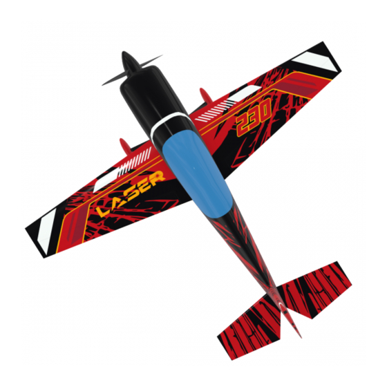
thank you for choosing LASER Z2300 Mk2 39% model airplane.
Original kit Laser Z2300 was developed by our team for Freestyle flight. Kit has had great flying
characteristics, but not sufficient for top competitive flying. We decided to improve it's flying
characteristic and that's why we created new version Mk2 built on strong base of current kit and test
it with our pilot Marek Plichta.
And what are the differencies?
At first, we made new bigger wings. Kit gets incredible flying agility also during harier manuvers..
Interier of the fuselage is also improved, holder of tanks which you can buy it with the plane and
already instaled rudder servo tray which you can extend with bearing arm. Holder of main landing
gear is also redesigned and for all control surfaces we used Gabriel horns.
The LASER Z2300 Mk2 kit is a full composite kit. Both wings and elevator should be easily
removed for transporting.
Content
1. Technical data ............................................................................................................................ 2
2. General informations................................................................................................................. 2
3. Setting and setup ..................................................................................................................... ..3
4. Recommended servos ............................................................................................................. ..4
5. Assembly ................................................................................................................................... 4
5.1 Empenage .................................................................................................................... 4
5.1.1 Rudder .......................................................................................................... 4
5.1.2 Horizontal stabilizator .................................................................................. 5
5.1.3 Elevator ........................................................................................................ 6
5.2 Wing assembly ............................................................................................................ 7
5.2.1 Servo install .................................................................................................. 7
5.2.2 Linkage ......................................................................................................... 8
5.3 Fuselage ..................................................................................................................... . 9
5.3.1 Rudder drive linkage .................................................................................. 9
5.3.2 Engine installation ..................................................................................... 10
5.3.3 Fuel & Smoke Tank installation ................................................................ 11
5.3.4 Equipment installation ................................................................................ 12
5.4 Landing gear .............................................................................................................. 12
5.4.1 Main landing gear ....................................................................................... 12
5.4.2 Tail wheel ................................................................................................... 14
5.5 Cowling and Cooling ............................................................................................... 15
LASER Z2300 Mk2 39%
Assembly Guide
1
page
Advertisement
Table of Contents

Summary of Contents for KRILL AIRCRAFT LASER Z2300 Mk2
-
Page 1: Table Of Contents
Holder of main landing gear is also redesigned and for all control surfaces we used Gabriel horns. The LASER Z2300 Mk2 kit is a full composite kit. Both wings and elevator should be easily removed for transporting. -
Page 2: Technical Data
1. Technical data: Wingspan 2800 mm Length 2662 mm Weight (RTF) 17 - 18 kg Wing area 132,5 dm2 Engine (Gas) 150-180ccm Minimum RC channels Number of servos 9 - 11 Notice: This Assembly guide only shows how the model could be assembled. According to model specification we expect, that this airplane is assembled by experienced user, which will use his habbits and skills to finish it. -
Page 3: Setting And Setup
KRILL model takes no responsibility for damages incurred during the assemblying, flying, using or transporting this model airplane. 3. Setting and set up Setting – incidence and CG Basic setup: deflection 20degrees, expo 50 – 60% Ailerons deflection 30degrees, expo 50 – 60% Elevator deflection 30degrees, expo 50 –... -
Page 4: Assembly
5. Assembly 5.1 Empenage 5.1.1 Rudder Gabriel horns 6/20 It´s so simple just glue the horns into the prepared holes using an epoxy resin. 5.1.2 Horizontal stabilizator Two operation for horizontal stabilizators is needed. First is to place the servo and drill the hole for servo lever. -
Page 5: Elevator
Second operation is to secure horizontal stabilizator against motion. This can be done two ways. First is to drill hole, which goes throught surface and carbon fiber tube (stabilizator spar). And place a pin (or screw) into this hole. This operation has to be done on both halfs! 5.1.3 Elevator Use Gabriel horns 6/27 size from accessories. -
Page 6: Servo Install
5.2 Wing 5.2.1 Servo instal First step is put the servos to the prepared holes and fix it with screws. Second step is stretch the cable (ONE4TWO) through the prepared holes in the wing and connect it to the servos. Then you should fix the MPX connector to the 3D printed holder and fix the holder into the prepared hole. -
Page 7: Linkage
5.2.2 Linkage Glue the supplied Gabriel horns size 6/27 into the prepared pair of holes with epoxy resin. Servo arm is connected with the Gabriel horn using a linkage made of a 60 mm long pushrod, terminated on one side by an original ball link from Gabriel horn and on the other side by a Secraft ball link. -
Page 8: Fuselage
5.3 Fuselage The installation of the internal equipment of the fuselage of the model is very individual, it depends on the habits of the builder, but especially on the equipment used, consider the following lines as informative, what the internal installation of the fuselage may look like. The model comes standard with a number of accessories that you can use: - Battery holders 5.3.1 Rudder drive linkage... -
Page 9: Engine Installation
5.3.2 Engine installation The MVVS 175NP engine was used for the model prototype shown. You can use any engine (2-cylinder boxer) size about 150-180 ccm. The engine is mounted offset to the right 2.5 degrees, horizontally at zero. It will probably always be necessary to mount the engine using spacers of suitable length so that prop hub plane is about 2-3 mm in front of the engine cover plane and respects the engine misalignment, on the engine axis at the prop hub level intersects the vertical axis of the model fuselage. -
Page 10: Fuel & Smoke Tank Installation
5.3.3 Fuel & Smoke Tank installation To install fuel and smoking tanks, you can use the standard delivered holder designed for use with Secraft square tanks - SE Fuel tank 1000 ml. The picture below shows an installation example. The tanks are attached to the holder with velcro... -
Page 11: Equipment Installation
5.3.4 Equipment installation No deck is instaled in the fuselage but it´s already prepared for one which you can use to mount your electronic system. For batteries (typically 2x RX batteries and 1x ignition batteries) you should use the standard delivered battery holders. The pictures below then represent a possible solution for the installation of on-board electronics, here a model equipped with JETI models electronics. - Page 12 The chassis leg and the wheel cover fit together exactly at the point of contact. First, drill the holes for the axles in both undercarriage legs as shown. Make a notch in the wheel cover to slide the cover onto the axle. When installing, first install the wheel with the axle on the chassis leg and then slide on the wheel cover before final tightening.
-
Page 13: Tail Wheel
5.4.2 Tail wheel assembly We recommend using our tail wheel 2010300-81 Tail wheel 35% with leg of C / F V2 for the model. Attach the tail wheel to the tail of the fuselage on a designated area, which is reinforced inside with plywood. -
Page 14: Cowling And Cooling
5.5 Cowling and cooling The engine cover (Cowling) is delivered in the kit as it is removed from the mold after production. The engine cover is only folded with the fuselage and there are holes for connecting screws to the fuselage.
Need help?
Do you have a question about the LASER Z2300 Mk2 and is the answer not in the manual?
Questions and answers