Advertisement
Quick Links
3
Safety regulations require that the device be switched on during
repairs. It is returned in its original condition and parts identical to
those specified are used.
English Version
CONTENTS
1. Table of Contents per page
2. Explanation of the Layout of the Documentation
3. Technical Specification
4. Controls
5. Repair Hints
6. Measurements and Settings
7. Exploded Views and Parts Lists of Mechanical
Components
8. Block Diagram, Principal Diagrams, Printed
Circuit Board Data
and Parts Lists of Electrical Components
9. Wiring Drawings
10. Trouble Shooting Methods
11. Changes
12. Additional Information
CHG 02/2023 v1.3
Advertisement

Related Manuals for Philips CD100


Summary of Contents for Philips CD100
- Page 1 CONTENTS 1. Table of Contents per page 2. Explanation of the Layout of the Documentation 3. Technical Specification 4. Controls 5. Repair Hints 6. Measurements and Settings 7. Exploded Views and Parts Lists of Mechanical Components 8. Block Diagram, Principal Diagrams, Printed Circuit Board Data and Parts Lists of Electrical Components 9.
- Page 2 TABLE OF CONTENTS PER PAGE Chapter Page Contents Chapter Page Contents Block Diagram Explanation of the layout of the Documentation Mains Filter Circuit Schematic Mains Filter PCB Drawing Technical Specification Controls Repair Hints Power Supply Circuit Schematic Power Supply PCB Drawing Bill Of Materials - Tools Removing the Frame Power Supply Circuit Schematic...
- Page 3 Chapter Page Contents Chapter Page Contents Servo Circuit Schematic (part 1) Decoder Circuit Schematic (part 2) List of Standard Symbols Servo PCB Drawing Wiring Drawing Wiring Drawing Servo PCB Drawing Fault Finding Method Fault Finding Method Fault Finding Method Servo Circuit Schematic (part 2) Fault Finding Method Fault Finding Method Servo Circuit Schematic (part 1)
-
Page 4: Technical Specification
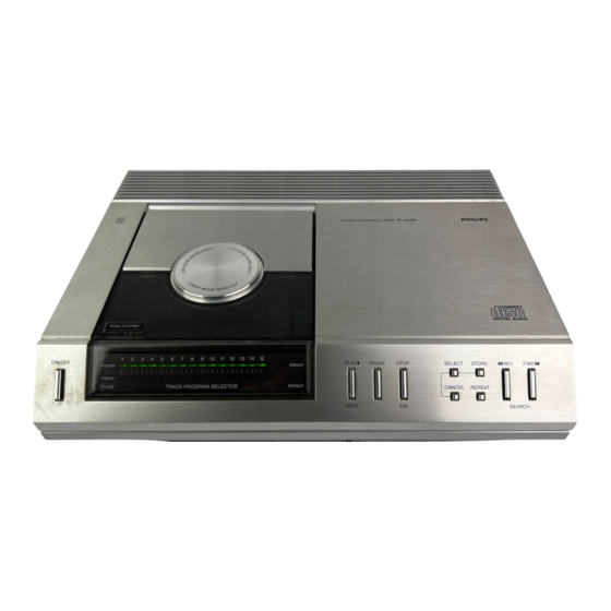
TECHNICAL SPECIFICATION • • ≥ 86dB Compact Disc Digital Audio System Channel Separation System • • 110V, 127V, 220V, 240V ± 10% < 0.3dB Mains Voltages Channel Difference (by changing transformer connections) • • 50, 60Hz (no switching necessary) < 0.005% (0dB) Mains Frequencies Total Harmonic Distortion •... - Page 5 CONTROLS 1. 'ON/OFF' button: for turning the player on and off. 9. 'STOP/CM' key: for intermittently stopping playback 2. 'PAUSE' LED: lights up when you press the ('STOP') and erasing a program ('CM' = Clear 'PAUSE' button. Memory) 3. 'PROGR' (amme) indicator: this indicates how many 10.
-
Page 6: Repair Hints
REPAIR HINTS To prevent loose metal objects from getting into the CD The servo-µp can be placed in the service position to check the mechanism, make sure that the repair area is clean. switch and display board and also to test the servo systems separately. - Page 7 Service Tools Support Services Separate test ICs Laser Simulator PCB For kit 1 NEG VOLT PH. SAA7000 POS VOLT SH 2. SAA7010 POS VOLT SH 3. SAA7020 Light Sensitive Components SAA7030 Photodiode TDA1540 L.D.R. (Light Dependent Resistor) Pusher Order Filter Screwdriver TORX Angle Mirror Straight...
- Page 8 Removing the frame • Take the frame out of the cabinet. • Remove the bottom plate after removing the 5 screws at the bottom. • Remove the 2 metal protective plates at the top of the frame. • Turn the player over. •...
- Page 9 CAUTION: To prevent settings from being changed, DO NOT Replacing the Lid loosen ANY SCREWS other than those mentioned • Remove the top cover (see "removing the frame"). above. • Remove the retainer from the valve switch and damper. • Press the detent tab and slide the damper shaft until a hinge THE LASER MECHANISM IS MUCH MORE SENSITIVE TO point is exposed.
- Page 10 MEASUREMENTS AND SETTINGS MECHANICAL MEASUREMENTS AND SETTINGS Height adjustment of the turntable (see Fig.) This setting requires the device to be in normal operating mode. Service supports 4822 395 30202 can be used for this Play from CD 4822 397 30086 track 1 or (CD without defects). Connect a DC voltmeter across resistor 3240 on the SERVO PCB.
- Page 11 Adjusting the angle setting When adjusting the angle of the plate-light path in the factory, a compromise was sought between minimal angular deviation and minimal friction of the arm. If the measurement shows that the angle falls outside the given tolerance, the angle must NOT be adjusted to a minimum deviation, but just within the tolerance.
- Page 12 ELECTRICAL MEASUREMENTS AND ADJUSTMENTS Adjusting the offset control Specification Measurement (see SERVO PCB) Put the servo-µp into service mode by simultaneously pressing the power switch and the stop keys. Connect a DC voltmeter between point 14 of IC6215 and ground. With resistor 3315 regulate the voltage to 0V.
- Page 13 Adjusting the focus bandwidth Laser power supply (NEG.VOLT.PH.) Since the light pen is very sensitive to static charges, when measuring and adjusting the laser power, the tools and yourself must have the same potential as the CD mechanism. Make a measurement setup according to the figure. Play from test CD 4822 397 30096 track 1 (CD without defects).
- Page 14 Laser power supply (POS.VOLT.SH.) PRE-AMP + LASER PCB marked with identification A06 and above Since the light pen is very sensitive to static charges, when Laser power supply (POS.VOLT.SH.) measuring and adjusting the laser power, the tools and yourself must have the same potential as the CD mechanism. Since the light pen is very sensitive to static charges, when measuring and adjusting the laser power, the tools and yourself must have the same potential as the CD mechanism.
- Page 59 • When switching on the mains voltage, connect the points 6 Selection of the ground potential If the lines are free of ground or supply voltage, then all keys TROUBLESHOOTING METHOD and 14 together. must be operable when the mains voltage is switched on. •...
- Page 60 The same difference must be measured at point <17>. If the (=FE) on the servo board, principal diagram C. b. Use a mobile phone camera and look for a tiny red dot. (=FE) on the servo board, principal diagram C. Note: In service loop B, the track is not only followed, but the signal at measurement point <17>...
- Page 61 • Bring the device into service loop B. Approximate measurement method IMPORTANT: c. Bring the device into service loop B. • Check whether there is activity on the bus (points 2 and 3 of (To be used in service loop A). If the device now functions, check the k-factor and the d- •...
- Page 62 First of all, the free-running oscillator should be checked and Annex IV: CHECKING THE k-FACTOR Annex V: CHECKING THE HF PRE-AMPLIFIER Repair procedure adjusted as follows: (Principal scheme E) (Measuring points on the servo print, principal diagram D) Since the light pen is very sensitive to static charges, the •...
- Page 74 11. AMENDMENTS Page changes Entered with A83-109 dated 1983-03-02 from cancellation A00. DESCRIPTION REASON Cover Sheet CD100/05 added Table of Contents Table of contents modified Table of Contents Added table of contents Specification Specification expanded and modified Repair Hints Text modified...
- Page 75 Entered with A84-118 dated 1984-04-20 DESCRIPTION REASON Cover Sheet CD100/30 added Table of Contents Table of contents modified Table of Contents Table of contents added Repair Hints Pusher code number changed Repair Hints Code numbers changed Repair Hints Service RAFOC unit changed...
- Page 76 Parts and PCB changes Entered with A84-118 dated 1984-04-20 CD100/00/05 SERVO PCB Reason PCB with Code Expired, added, modified Improving focusing startup. C2213 added (100nF) C2259 changed to 15nF Improved stability. C2251 changed to 470nF C2244 changed to 560pF R3328 changed to 270k...
- Page 77 DECODER PCB Reason PCB with Code Expired, added, modified R3501, 3502, 3504 and 3508 changed to 8M2 Improved drop-out behaviour. R3503. 3507 changed to 18k R3305, 3509 changed to 180k R2505 changed to 2k7 New Erco IC (M4281). Stabilizer PCB for the power supply of Erco circuit expired.
- Page 78 Stabilizer PCB for the power supply of the Erco circuit has New Erco IC (M4281). been discontinued. Demod-Erco interface PCB applied. Decoding PCB has been changed from A01 to A02. CD100/30 SERVO PCB Reason PCB with Code Expired, added, modified C2217 changed to 3.3µF...
-
Page 79: Additional Information
12. ADDITIONAL INFORMATION Pre-amplifier board + light pen (POS. VOLT. SH.) Service position of the decoder panel With effect from version number A06, the PCB layout of the pre-amplifier Decoder panels that are NOT provided with service PCBs may print has been changed and a new light pen is used in combination with NOT be placed in the horizontal service position (as given on page this. - Page 80 Already published A83-109, A83-111, A83-134, A84-118 The following pages have been changed/added to adapt the Service Manual. Change Sheets 1-1-f 1-2-d 8-7-2-a 8-11-3-a 11-2-a...
- Page 81 TABLE OF CONTENTS PER PAGE Chapter Page Contents Chapter Page Contents Explanation of the layout of the Block Diagram Documentation Mains Filter Circuit Schematic Technical Specification Mains Filter PCB Drawing Controls Repair Hints Power Supply Circuit Schematic Power Supply PCB Drawing Bill Of Materials - Tools Removing the Frame Power Supply Circuit Schematic...
- Page 82 Chapter Page Contents Chapter Page Contents Servo Circuit Schematic (part 1) Decoder Circuit Schematic (part 2) List of Standard Symbols Servo PCB Drawing Wiring Drawing Wiring Drawing Servo PCB Drawing Fault Finding Method Fault Finding Method Fault Finding Method Servo Circuit Schematic (part 2) Fault Finding Method Fault Finding Method Servo Circuit Schematic (part 1)
- Page 87 11. AMENDMENTS Page changes Entered with A83-109 dated 1983-03-02 from cancellation A00. DESCRIPTION REASON Cover Sheet CD100/05 added Table of Contents Table of contents modified Table of Contents Added table of contents Specification Specification expanded and modified Repair Hints Text modified...
- Page 88 Entered with A84-118 dated 1984-04-20 DESCRIPTION REASON Cover Sheet CD100/30 added Table of Contents Table of contents modified Table of Contents Table of contents added Repair Hints Pusher code number changed Repair Hints Code numbers changed Repair Hints Service RAFOC unit changed...
Need help?
Do you have a question about the CD100 and is the answer not in the manual?
Questions and answers