Table of Contents
Advertisement
Quick Links
Advertisement
Table of Contents

Summary of Contents for Euroscan X3
- Page 1 Installation & Operation Manual X3 Document Number: PRO.020 Revision: 1.0 ...
- Page 2 © 2015 Euroscan —All Rights Reserved. This publication, or any part thereof, may not be reproduced or transmitted in any form or by any means, electronic or mechanical, including photocopying, recording, storage in an information retrieval system, or otherwise, without prior written permission by Euroscan. Trademark Notice The Euroscan Company logo is a trademark of Euroscan B.V. All other product names used throughout this material are trademarks of the respective companies. No such use of any trademark is intended to convey endorsement or other affiliation with these companies. Disclaimers This document is the proprietary and exclusive property of Euroscan except as otherwise indicated. No part of this document, in whole or in part, may be reproduced, stored, transmitted, or used for design purposes without the prior written permission of Euroscan. This document contains technical information and descriptions of the ORBCOMM System that reflect the status of the system design and/or planned design as of the date of issue. The contents of this document are subject to change without notice, and no warranty or representation, expressed or implied, is made with respect to its contents. 2 Installation & Operation Manual X3, PRO.020 ...
-
Page 3: Table Of Contents
1.7 Intended use statement ............................. 7 1.8 Safety Guidelines .............................. 8 1.9 WEEE Statement .............................. 8 1.10 Customer Care .............................. 8 2. Installation ................................ 9 2.1 Package Content .............................. 9 2.1.1 Euroscan RX3 ............................... 9 2.1.2 Euroscan TX3 ............................. 1 0 2.2 Requirements .............................. 1 0 2.3 Connections .............................. 1 1 2.3.1 Connector block 1 (power supply and outputs) .................. 1 2 2.3.2 Connector block 2 (serial port) ........................ 1 3 2.3.3 Connector block 3 (digital inputs) ...................... 1 3 ... - Page 4 4. Maintenance ................................ 5 2 4.1 Inspection ................................. 5 2 4.2 Error codes ................................ 5 2 4.3 RMA .................................. 5 2 4.4 Replace paper roll ............................. 5 3 4.5 Euroscan TX3 / RX3 recorder calibration ...................... 5 4 4.6 Euroscan TX3 / RX3 recorder temperature verification ................... 5 5 4.7 Technical specifications ............................ 5 7 4.7 Removing the Unit ............................ 5 8 4.7 Liability ................................ 5 8 ...
-
Page 5: About This Installation Manual
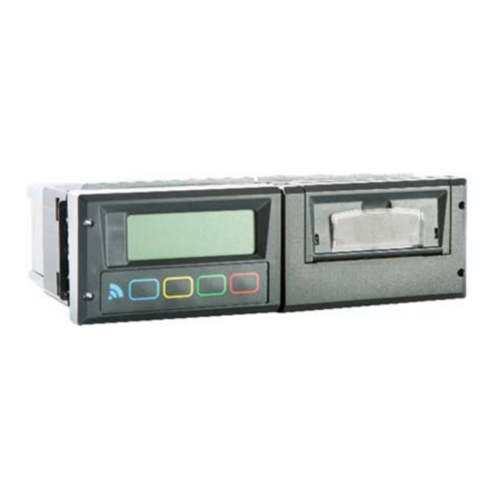
This manual contains information about Euroscan TX3 / RX3 recorders. No representations or warranties are made as to the accuracy or completeness of the information contained herein. No representation or warranties are made as to the completeness and compliance of any installations, which are performed using this manual. 1.2 Purpose This manual contains detailed installation information for and operation of the Euroscan TX3 / RX3 recorders. Please follow the instructions and recommendations of this manual for a proper installation. Improper installations will void the product warranty. The intended audiences for this manual include field support personal, product evaluators and certified third‐party personnel. It is particularly intended for personnel who are responsible for system installation and activation. In addition, and is appropriate, this manual may be used for customer training purposes. Fig. 1 RX3 Fig. 2 TX3 5 Installation & Operation Manual X3, PRO.020 ... -
Page 6: Revision History
1.4. Regulations Only Euroscan trained and qualified personnel should be allowed to install, replace or service the recorder. The Euroscan certified installer needs to perform the installation of the recorder complying with at least the following: This installation and operation manual and other relevant documentation provided by the manufacturer. EMC Directive 2004/108/EC. Low Voltage Directive 2006/95/EC. Harmonized standards under Directive 1999/5/EC. WEEE Directive 2012/19/EU. Traffic regulations of the country of installation and countries in which the recorder will be used. Regulations and instructions described in the installation and operation manual of any supplementary device(s). 1.5 Document conventions Below are some ‘common ground’ conventions which are used in this document; Will be used when referring to exact recorder menu items or options [] Will be used to indicate buttons, such as <Print> button. <> Caution Will be used to indicate an explicit message possibly resulting in injuries, unexpected behavior or damaged hardware Operator alert Will be used to indicate a message which needs special attention 6 Installation & Operation Manual X3, PRO.020 ... -
Page 7: Terminology
OC Open circuit SC Short circuit 1.7 Intended use statement The recorder is designed to safely operate under the following conditions: Operating voltage: 10‐32 VDC (negative earth), protected against alternator load shedding. Temperature in operation : ‐30 °C / +70 °C (‐22 °F / 158 °F) Temperature maximum : ‐40 °C / +85 °C (‐40 °F / 185 °F); Humidity: 97% relative humidity at 25 °C (77 °F). No special ventilation requirements. Euroscan recorders are designed for use in an automotive environment. For protection a 10A floating fuse must be fitted in the positive (+VE) power line as close as possible to the power connection (provided in installation kit). Use of this product in adverse conditions will void the product warranty. ... -
Page 8: Safety Guidelines
Do not expose the Euroscan RX3 recorder to rain or moisture Do not expose the Euroscan TX3 recorder (the inside) to rain or moisture during installation Do not install near heat sources such as exhaust pipes. Only use accessories specified by the manufacturer. Do not use the recorder if it has been physically damaged or shows to be abused. A lithium battery is used in the recorder. Do not try to charge, discharge or replace this battery. Do not work on the installation when the recorder is connected to a power supply, except when connecting the antenna(s) (see ESD warning for the Euroscan RX3 installation instruction). 1.9 WEEE Statement Ultimate disposal of this product should be handled according to all national laws and regulations. The mark shown to the right is in compliance with Waste Electrical and Electronic Equipment Directive 2002/96/EC (WEEE). The mark indicates the requirement NOT to dispose the equipment as unsorted municipal waste, but use the return and collection systems according to local law. 1.10 Customer Care Review entire installation manual before proceeding. Please contact Customer Care at +49 (0) 228‐926380 should there be any questions during the replacement. 8 Installation & Operation Manual X3, PRO.020 ... -
Page 9: Installation
Recorder 1 Temperature sensor (15mtr) 1 Temperature sensor (22mtr) 1 Safety bracket temperature sensor (protection guard) 1 Power cable (black/red/yellow) 1 ISO 7736 installation kit 1 Waterproof 10A fuse bracket including 10A fuse 2 Removal keys 1 Phoenix 8 connector 1 Phoenix 6 connector 1 Screw M3 x 20 1 Nut M3 1 O‐ring M4 2 Temperature sensor clamps 1 PRO.018.X3 Quickstart guide 1 PRO.019.X3 Safety instructions 1 PRO.037.X3 Certificate of conformity 9 Installation & Operation Manual X3, PRO.020 ... -
Page 10: Euroscan Tx3
1 Waterproof 10A fuse bracket including 10A fuse 4 Blind nut 4 Screw M5 x 30 1 Phoenix 8 connector 1 Phoenix 6 connector 1 Screw M3 x 20 1 Nut M3 1 O‐ring M4 2 Temperature sensor clamps 1 PRO.018.X3 Quickstart guide 1 PRO.019.X3 Safety instructions 1 PRO.037.X3 Certificate of conformity 2.2 Requirements Power supply 12‐24VDC (negative earth) Preferable radio slot and/or IP20 proof location available for Euroscan RX3 Free IP65 proof mounting location on trailer for Euroscan TX3 (International traceable) calibration equipment Appropriate working tools for applying the installation ... -
Page 11: Connections
Digital Sensor D2 (+) Pin 4: Digital Sensor D2 (‐) Pin 5: Digital Sensor D3 (+) Pin 6: Digital Sensor D3 (‐) Pin 7: Digital Sensor D4 (+) Pin 8: Digital Sensor D4 (‐) Connector 4: Pin 1: GND Analog Temperature Sensor (T1,T2,T3) (‐) Pin 2: T1 Analog Temperature Sensor (+) Pin 3: T2 Analog Temperature Sensor (+) Pin 4: T3 Analog Temperature Sensor (+) Pin 5: GND Analog Temperature Sensor (T4,T5,T6) (‐) Pin 6: T4 Analog Temperature Sensor (+) Pin 7: T5 Analog Temperature Sensor (+) Pin 8: T6 Analog Temperature Sensor (+) 11 Installation & Operation Manual X3, PRO.020 ... -
Page 12: Connector Block 1 (Power Supply And Outputs)
2.3.1 Connector block 1 (power supply and outputs) Power supply Connect power supply on pin 1 (+) and pin 2 (‐). The recorder is suitable for a voltage between 10‐32 VDC (negative earth). Power consumption when printing is 25W. Display background light (preferable for the Euroscan RX3) Usually the display background light switches on after pressing any key and switches off automatically after some seconds if no further key is pressed. If a permanent background light is required while driving connect pin 3 to a vehicle ignition +signal. Never connect display background light directly to vehicle battery! Alarm outputs Pin 4 is a digital alarm output. The output switches to ground in case of an alarm situation and is limited to 1A output current. Below are two examples of how the digital alarm can be connected. Option 1 Option 2 Option 2 is recommended in case an alarm is chosen which has peak currents higher than 1A 12 Installation & Operation Manual X3, PRO.020 ... -
Page 13: Connector Block 2 (Serial Port)
Euroscan TX3 / RX3 recorders offer the possibility to connect up to 6 temperature sensors. Pins 1‐8 are accordingly marked with T1‐T6. Pins 2, 3, 4, 6, 7 and 8 are signal inputs and pins 1 and 5 are internally connected to ground. The polarity of the sensor cable is not relevant. In the factory settings inputs 1 and 2 are activated and pre‐programmed as follows: T1 = return air, T2 = rear. Please note that a used input always has to be activated and configured in the parameter menu. Never use tinned wire ends in the phoenix connectors of the recorders. You can apply a ferrule on the stranded wire or fold back the stranded wires over the isolation and fully insert in the phoenix connector (so isolation included). 13 Installation & Operation Manual X3, PRO.020 ... -
Page 14: Mounting
2.4.2 Temperature sensors Euroscan TX3 / RX3 recorders can only be used with Euroscan temperature sensors as supplied with the Euroscan package. Before installation, it is necessary to determine how many measurement points are required to retrieve the desired information. Only with an optimal choice of the number and position of the sensors a sensible conclusion can be drawn about the air temperature in an entire compartment. The following must be observed before planning the installation of the temperature sensors: ‐ The temperature sensor should not be mounted in a location without air circulation. ‐ The sensor position should be protected against bumping of load, doors, etc. ‐ The channel of the interior light must have a minimum distance of 0.5 m to the sensors. ‐ We recommend at least one sensor per compartment and also one sensor in the return air flow. The best position of a compartment sensor is in the middle under the ceiling at about 1/3 of the compartment length measured from the back. ‐ The compartment sensor should be mounted with the Euroscan protection guard, which will allow sufficient air circulation around the sensor. ‐ For future calibration requirements, it is advisable to allow enough spare cable to enable the sensor to be lowered to the floor. 14 Installation & Operation Manual X3, PRO.020 ... - Page 15 Example installation on a truck Example installation on a trailer 15 Installation & Operation Manual X3, PRO.020 ...
-
Page 16: Digital Inputs
Switched to battery 2 (+) (high) Switched to ground (‐) 3 (low) Digital input distinct between high levels and low levels around 5 volts. A voltage level lower than 4 volts is low level, a level higher than 6 volts is high level. The digital active can be matched to low or high level in menu 6 of the recorder. 2.4.4 GPS Please keep the following in mind when mounting a recorder with internal antenna or an external antenna: ‐ Always mount horizontally with the reception surface looking up. ‐ Do not choose a location covered by metal, metal containing components or paint. Also pay attention to windows in which metal film is processed. ‐ Mount in clear sight. ‐ Wiring should be free of obstacles, kinks or dents. This could be of influence to the performance of the reception antenna cable. ‐ Mount in an interference free location Testing of the GPS signal cannot be compared to reception on smart phones. These use the assisted GPS technology in which location detection is used via cell towers and WiFi. 16 Installation & Operation Manual X3, PRO.020 ... -
Page 17: Recorder
All drilled holes need to be sealed with a suitable sealant. Euroscan RX3 The Euroscan RX3 recorder is designed to be mounted within the cabin of a vehicle in a single DIN radio slot (according to ISO 7736). Optional mounting kit If no radio slot is available the recorder should be mounted with the optional mounting kit (P/N: 001.000.1202 RX mounting frame non metal). This will replace a radio slot and can be fixed either on or under the dashboard as well as on the back wall. Ensure that the position chosen allows the driver to see the display and use the operator keyboard. Please keep in mind that access to the printer is required to replace the paper roll. 17 Installation & Operation Manual X3, PRO.020 ... - Page 18 Installation Instruction Euroscan RX3: When installing an Euroscan RX3 unit with a communication module, prevent Electrical Static Discharges (ESD) damage by connecting the power before connecting the GPS + GPRS antennas. 1. Select a suitable position for the Euroscan RX3 recorder, for example a free car radio slot in the dashboard, or above the driver. If there is no free slot, we recommend our optional mounting kit with P/N: 001.000.1202 RX mounting frame non metal. The mounting kit can be fitted on top, or underneath the dashboard. 2. Next, push the mounting frame into the slot and bend the metal flaps to secure its position. 3. Install the sensors from the body to the driver’s cabin. Please ensure you fit the cables along the chassis with the harness, so that they won’t break when tilting the cabin. 4. Take the connector blocks off the back of the instrument and fix the cables according to the wiring diagram (see section 2.3). 5. Connect the power supply via the 10A fuse provided, directly to the main vehicle battery, the recorder will start recording automatically. 6. Now attach, where applicable, the GSM/GPS antenna. Ensure adequate power is supplied permanently to the recorder at all times. 7. Finally, before pushing the instrument into the slot, we recommend you test the functionality and do a printout. ...
- Page 19 Cables should be installed via watertight cable glands. This avoids humidity penetration into the box. For each cable a separate gland should be used unless you use a gland especially designed for more cables. Installation Instruction TX3: 1. Mark four holes at the front of the body in an easily accessible location (usually underneath the refrigerator unit to the right or left hand side). Then drill holes with a 10mm drill. 2. Insert the four rubber mounting nuts. Mount recorder using the four screws and washers provided (note metal washer to be located on the outside of the mounting lug fixed to the box). Ensure screws are screwed in tight. Use any available entrance for the temperature sensors. If no entrance is available, drill a hole large enough at suitable location through bulkhead to pass the temperature sensors through. Please make sure that the cable glands of the box show downwards. 3. Position sensor no. 1 to the return air (RET.AIR) usually next to the refrigerator sensor, but only if good airflow is around it, otherwise locate sensor onto grill. 4. Position sensor no. 2 at high level usually to the roof, either in the center or to the side, 2 ‐ 3 meters in from the rear doors. 5. Ensure all cables are installed neatly into plastic channels or similar. Ensure that there is at least 1 ‐ 2 meters of spare cable in channels, this will facilitate calibration. 6. Connect power cable through the 10A fuse provided, directly to the main vehicle or refrigerator battery, recorder will start recording automatically. 19 Installation & Operation Manual X3, PRO.020 ...
- Page 20 7. Ensure all holes drilled through the body are sealed with a suitable sealant. 20 Installation & Operation Manual X3, PRO.020 ...
-
Page 21: Antenna Installation Position
2.4.6 Antenna installation position Mount the TX bracket or magnetic antenna in a position that the black top of the antenna has a clear line of sight to the satellites above. Also make sure that the 3G/GPRS antenna has a clear line of sight as well. Stick the RX antenna on the inside of the windscreen and make sure that it has a clear view to the sky above. • Do NOT let the antenna hang on the connection cable • Do NOT mount the antenna and wiring close to a heat source (like heating channels or exhaust pipes) • Do NOT cut or extend or make any changes to the cables • Do NOT curl up cables • Do NOT bend the cables in sharp angles as this might break the core of the wire • Make sure that the antenna has a clear view to the sky (towards the satellites) • Place cables into a cable gutter • Do not place the antenna too close to toll systems • Please install the antenna according to the installation standards (and not directly in the drivers view) 21 Installation & Operation Manual X3, PRO.020 ... - Page 22 Only for TX: Make sure the antenna leads into the two holes of the cable gland as shown in the picture on the right. Then attach the cable gland to the trailer box with the included M20 nut. Connect power cables before connecting all other connectors (including antenna) and put the recorder into the radio slot (RX) or trailer box (TX). Only for TX: ‐ fasten the recorder inside the plastic trailer box with the 4 black screws and washers. RX (Back) TX (Left side) Only for TX: Now tighten the cable gland, leaving enough wire (10 cm) inside the trailer box to allow for easy access. 22 Installation & Operation Manual X3, PRO.020 ...
- Page 23 2G MODULE + GPS 2G/3G Module + GPS Part number: 006.000.9003 Make sure that any work on the recorder is done at an ESD save workstation. Failing to do so will damage the equipment beyond repair and void the warranty. While working on the recorder, it should be disconnected from power. 3G modules are only suitable in Euroscan X3 / X2‐6 units that perform on Platform 7 23 Installation & Operation Manual X3, PRO.020 ...
- Page 24 3) Enter the menu 11.4.1 “GPRS settings” a) If applicable please provide the pin‐code of the SIM card. 4) Go to Menu 11.4.1.3 to the “APN server” a) You can choose one of the APN pre‐sets that are available in the recorder by pressing [<] [>]. Or set it to “Manual input” if you want to provide your own APN settings for this particular SIM‐card b) Make sure to enter the specific values of your SIM‐card a. “APN server”/ “APN user” / “APN Password” c) We recommend leaving the DNS settings blank 5) To apply the configuration the recorder needs to be rebooted. 6) To install the SIM‐card, please take the power off the recorder 7) Install the SIM‐card in the SIM‐cardholder on the backside of the recorder a) Press the yellow push button down into the recorder, to have the SIM‐card holder released b) Place a SIM‐card in to the holder and place the holder with SIM‐card back into the recorder 8) Power on the recorder again If you run into problems while bringing the unit online you can trouble shoot with the “EN‐WHT‐0004 ‐ Bringing a unit online” document that you can request from your distributor! 24 Installation & Operation Manual X3, PRO.020 ...
-
Page 25: Configuration
Press the <red button> to return to the normal display. Vehicle ID The vehicle ID will appear on printed tickets: ‐ Press and hold the <green button> for 4 seconds to get into the parameter mode. ‐ Enter the PIN code 1111 by pressing the <blue button> 4 times. ‐ Select menu 10.5 [Vehicle ID] and press the <green button>. ‐ Now enter the vehicle ID. ‐ Press the <green button> and the <red button> simultaneously to accept. ‐ Press the <red button> 2 times to return to the normal display Header text The header text will appear on printed tickets and is usually used for defining the customer’s name. ‐ Press and hold the <green button> for 4 seconds to get into the parameter mode. ‐ Enter the PIN code 1111 by pressing the <blue button> 4 times. ‐ Select menu 10.6 [Header text] and press the <green button>. ‐ Now enter the customer’s name. ‐ Press the <green button> and the <red button> simultaneously to accept. ‐ Press the <red button> 2 times to return to the normal display 25 Installation & Operation Manual X3, PRO.020 ... -
Page 26: Testing
The following items are to be checked if applicable: Printer Test the printer by printing any ticket. Status inputs For each activated status input a small box appears in the top right hand of the display (pre‐defined symbol, indicating that the corresponding input has been activated). If the status of the input changes a symbol can be chosen instead of the box. This symbol appears and disappears according to the change of the status. = Defrost inactive = Defrost active = Refrigeration inactive = Refrigeration active | = Back door / Side door closed = Back door / Side door open = Battery back‐up active/low charge – the recorder is working on normal power = Battery back‐up active/high charge – the recorder is working on backup battery = Free text active 26 Installation & Operation Manual X3, PRO.020 ... - Page 27 Alarm signal The internal alarm signal (persistent buzzer) can be heard as soon as a defined temperature threshold has been exceeded. In case of an alarm an external signal is also activated if this is installed. Furthermore the corresponding temperature input will flash on the display. The internal signal buzzer can be switched off by pressing the yellow (alarm) key. The external signal and the flashing display will only stop after the temperature is back within the defined limits. Advanced For testing advanced features like refrigerator connections, the terminal function in EuroTool is available. 27 Installation & Operation Manual X3, PRO.020 ...
-
Page 28: Operating This Unit
GPRS modem... For further information please contact the Euroscan sales team or visit our website at www.euroscansupport.com. Check the correct functioning of the recorder frequently (minimum – together with the refrigerator service). Check the recording system every 12 months to see if the temperature measurement error is within the maximum permissible error. The annual test is obligatory, according to resp. EN 12830 or EN 13486. Do not weld without disconnecting the power from the Euroscan TX3 / RX3 recorder or the vehicle. Do not take the power supply from a generator system without extra filter protection against high voltage peaks. Preferably, always take power direct from the vehicle or refrigerator battery. Follow the installation and user instructions in this manual. 3.1 Euroscan recorder EUROSCAN RX‐3 The Euroscan RX3 has been developed for mounting in a vehicle cabin. The chassis of the recorder meets the dimensions of a DIN car radio and can be easily mounted in a free available radio slot EUROSCAN TX‐3 The Euroscan TX3 has been developed especially for mounting outside on a box body or trailer. The unit is contained in a waterproof plastic box (IP65). As on the Euroscan RX3, the connectors are on the back of the unit. Cabling is installed through watertight cable glands, which are mounted in the recorder box. The control panel of the Euroscan TX3 / RX3 consists of 3 main components: 1. LCD display 2. Keyboard 3. Printer (optional) 28 Installation & Operation Manual X3, PRO.020 ... - Page 29 6. Mobile Temperature probe 7. Door detection sensors 3.1.1 LCD Display The display has four lines of information, showing the following content in the operating mode. Line 1 : Alarm activated; temperatures; status of digital inputs –15 –22 Line 2 : Rotating display of each active temperature with 1:Return air –22.8 ºC sensor name Line 3 : Day, date and time with indication of THURSDAY 14/02/2015 11:39:29 W summer/wintertime Line 4 : Description of the actual button functions In every other mode the content of the display is dependent on the actual menu in use. 29 Installation & Operation Manual X3, PRO.020 ...
-
Page 30: Printer
In edit mode: cancel input and display the non‐ changed value. Press 4 seconds for rejecting input and go back to previous menu. When entering free programmable text, such as names, the button functions are as follows: Blue Next character from the list Yellow Previous character from the list Green < One character to the left Red > One character to the right Blue + <‐Cncl Cancel input and display the non‐changed value. Yellow Press for 4 seconds to reject the input and go back to the previous menu. Green + accept Accept input and go to next menu point. Red 3.1.3 Printer The thermal printer is installed on the right side of the recorder. For more details about replacing the paper roll, please refer to chapter 0 4.4 Replace paper roll. 30 Installation & Operation Manual X3, PRO.020 ... -
Page 31: Bluetooth
Make sure you are within a few meters of the recorder when connecting. Step 1) Plug the dongle into a USB port. Step 2) Wait for Windows to install the drivers. Step 3) After Windows successfully installed the drivers, a Bluetooth icon should appear in your taskbar notification area. Step 4) Right click on the Bluetooth icon and select “Open Settings”. Step 5) Make sure your checkboxes are checked like in the picture below (Uncheck the “Alert me when a new Bluetooth device wants to connect” box): 31 Installation & Operation Manual X3, PRO.020 ... - Page 32 Step 7) Go to the “Local” tab. Wait for the dongle to detect recorders. This may take a few minutes. Step 8) Select the recorder and click on “Connect”. Wait for EuroTool to establish the connection. If the wanted recorder is not listed, click on “Scan” to rescan. This will take about 10 seconds. Step 9) EuroTool is connected to the recorder when a similar screen is displayed. 32 Installation & Operation Manual X3, PRO.020 ...
-
Page 33: Low Power Mode
User settings menu Status menu (Menu ‐ 1) Print menu Press the <blue button>. The last selected print choice will be displayed. Delivery ticket Printing now starts after 4 seconds. Repeatedly pressing the <blue CURRENT VALUES button> will scroll between the available print options: delivery ticket, journey ticket graphical, journey ticket numerical and historical ticket. <‐CNCL By holding the <blue button> for more than 4 seconds the following sub‐menus can be reached: (M ‐ 1.1) Select compartment to print 1.1 Select compart- By pressing the <green button> you confirm that you wish to change ment to print the settings. The chosen compartment can be selected by pressing (Compartment 1) < > and your choice can be confirmed with ACCEPT EDIT <‐MENU 33 Installation & Operation Manual X3, PRO.020 ... - Page 34 (dd/mm/yyyy) you select the time period of your historical report. Pressing the <green button/ ACCEPT> for the 3 time lets you choose what report you want to have printed. You can change the EDIT <‐MENU report by pressing the <blue> or <yellow button>. Printing starts after a delay of 4 seconds. (M ‐ 1.6) Delivery ticket setting 1.6 Delivery ticket With EDIT you can set the desired information printed on the setting delivery ticket. You can select “Actual only”, “Actual + average” or (Actual+average) “Actual+avg. +min/max”. By pressing the <green button> you ACCEPT your choice. ACCEPT <‐MENU (M ‐ 1.7) Print time period 1.7 Print time period With this option you define the total print period. (10 hour(s)) EDIT <‐MENU 34 Installation & Operation Manual X3, PRO.020 ...
-
Page 35: (Menu - 2) Alarm Settings
The printed ticket will never be longer than the print time period as defined in (M ‐ 1.7) Print time period. Example: The journey marker is set on 13:00h and the print time period is set to 2 hours. If a ticket is printed on 14:00h, the start time will be 13:00h. If a ticket is printed at 15:30h, the start time will be 13:30h. (Menu ‐ 2) Alarm settings Up to four different alarm types can be assigned to four different compartments. The various alarms (and compartments) are only available if the supervisor has preset and configured them in the parameter menu. Alarms Press the <yellow button> to access the alarm menu where you have Comp 1 Comp 2 direct access to compartment 1 + 2. OFF OFF XX XX X 35 Installation & Operation Manual X3, PRO.020 ... - Page 36 (M ‐ 2.2) compartment 2 (The same as compartment 1) (M ‐ 2.3) compartment 3 (The same as compartment 1) (M ‐ 2.4) compartment 4 (The same as compartment 1) (M ‐ 2.5) Digital input 1 2.5 Digital 1 The Euroscan TX3 / RX3 recorders are provided with 4 digital inputs. (On) These inputs can be used for invoking alarms from door switches and refrigerator’s. The alarm condition is reached if an input remains in an alarm condition for a certain period of time. This preset (delay time) < > ACCEPT <‐CNCL can be setup to 60 minutes. (M ‐ 2.6) Digital input 2 (The same as Digital input 1) (M ‐ 2.7) Digital input 3 (The same as Digital input 1) (M ‐ 2.8) Digital input 4 (The same as Digital input 1) (M ‐ 2.9) Alarm output test By pressing the <green button/ TEST> you will initiate the external alarm for 10 seconds. This is the A0‐output on the back of the recorder. You could connect this to a light or buzzer for extra signaling. 36 Installation & Operation Manual X3, PRO.020 ...
-
Page 37: (Menu - 3) User Settings Menu
3.5 Select language Select the desired language with < > and confirm with (English) ACCEPT. < > ACCEPT <‐CNCL (M ‐ 3.6) Set display contrast 3.6 Set display Set the desired display contrast with < > and confirm contrast with ACCEPT. If you set this value to low, you might not see anything on the display < > ACCEPT <‐CNCL (M ‐ 3.7) Set display backlight 3.7 Set display Set the intensity of the backlight to your convenience backlight with < > and confirm with ACCEPT. This applies to the display backlight that switches on when you press any button. When pressing no button, the backlight automatically switches off after 30 < > ACCEPT <‐CNCL seconds. 37 Installation & Operation Manual X3, PRO.020 ... - Page 38 Change the buzzer frequency with < > and confirm frequency with ACCEPT. This only applies to the sound of the keys being pressed, and not to alarms. < > ACCEPT <‐CNCL (M ‐ 3.10) Set buzzer on‐time 3.10 Set buzzer Change the buzzer on‐time with < > and confirm with On-time ACCEPT. This only applies to the sound of the keys being pressed, and not to alarms. < > ACCEPT <‐CNCL TMS X3 V3.29.0 (M ‐ 3.11) TMS X3 Vx.xx.x © dd/mm/yyyy hh:mm Displays the current firmware version of the recorder Checksum: XXXX <‐MENU ...
-
Page 39: (Menu - 4) Status Menu
Parameter Settings 6 Digital inputs settings ENTER PINCODE 7 compartment settings 8 Alarm settings 9 Printer settings ‐1‐ ‐2‐ ‐3‐ ‐4‐ 10 General settings 11 Communication settings A 4 digit PIN code has to be entered in order to enter menus 5 to 11. 39 Installation & Operation Manual X3, PRO.020 ... -
Page 40: (Menu - 5) Temperature Input Settings
The inputs for temperature measurements can be switched on/off and assigned a name. Depending on the sensor position the default input 1 is preset as ‘Return air’ and input 2 as ‘Rear’. (M‐5.1) T1 input If set to „on“ input 1 will be measured, displayed and stored into memory. Printing of input 1 is assigned in the compartment setting (menu item 7). When set to ‘Off’, the following points will not be an option in the menu (M‐5.1.1) Type There are several types of sensors that you can select here that will function as your data input. Please make sure you are using the correct type for the connected or mapped information. Physically connected sensors on the X3 Temp. 110 (-10 to +110 Degrees Celsius) Temp. 500 (-5 to +500 Degrees Celsius) Temp. Standard (-50 to +70 Degrees Celsius) (Default) Relative Humidity (0..1 V) Universal (0..2,5 V) - Page 41 < ‐ c n c l ` a c c e p t (M ‐ 5.2) T2 input < > (The same as T1 input) (M ‐ 5.3) T3 input (The same as T1 input) (M ‐ 5.4) T4 input (The same as T1 input) (M ‐ 5.5) T5 input (The same as T1 input) (M ‐ 5.6) T6 input (The same as T1 input) 41 Installation & Operation Manual X3, PRO.020 ...
-
Page 42: (Menu - 6) Digital Inputs
< ‐ C N C L ` A C C E P T < > 42 Installation & Operation Manual X3, PRO.020 ... - Page 43 COM1: External 1 connected devices to be placed on this input. This only applies for the last 4 Activation inputs (External sensor, Transcan, Datacold < > ACCEPT <‐CNCL 500, Fridge) You select what input (1..9) you want to read from what com‐port (Com1 & Com2) with < > and confirm with ACCEPT. We recommend using EuroTool 7 for easier setup! 6.1.5 Alarm (M ‐ 6.1.5) Alarm Set to “ON” in order to activate an alarm for this input when this input is active. < > ACCEPT <‐CNCL (M ‐ 6.1.6) Alarm Delay time 6.1.3 Delay time The delay time given in minutes before the Alarm is activated. 0:30 hour(s) < > ACCEPT <‐CNCL 43 Installation & Operation Manual X3, PRO.020 ...
-
Page 44: (Menu - 7) Compartment Settings
7.1.2 Print T1 when printing the delivery ticket. < > ACCEPT <‐CNCL (M ‐ 7.1.3) Alarm on T1 7.1.3 Alarm on T1 Choose whether T1 will be monitored in this compartment when an alarm group is assigned. < > ACCEPT <‐CNCL (M ‐ 7.1.4) Print T2 (Same as Print T1) (M ‐ 7.1.5) Alarm on T2 (Same as Alarm T1) (M ‐ 7.1.6) Print T3 (Same as Print T1) (M ‐ 7.1.7) Alarm on T3 (Same as Alarm T1) (M ‐ 7.1.8) Print T4 (Same as Print T1) (M ‐ 7.1.9) Alarm on T4 (Same as Alarm T1) 44 Installation & Operation Manual X3, PRO.020 ... - Page 45 (Same as Print T1) (M ‐ 7.1.11) Alarm on T5 (Same as Alarm T1) (M ‐ 7.1.12) Print T6 (Same as Print T1) (M ‐ 7.1.13) Alarm on T6 (Same as Alarm T1) (M ‐ 7.1.14) Print D1 Choose where D1 will be monitored for an alarm state (not dependent on alarm group) (M ‐ 7.1.15) Print D2 Choose where D2 will be monitored for an alarm state (not dependent on alarm group) (M ‐ 7.1.16) Print D3 Choose where D3 will be monitored for an alarm state (not dependent on alarm group) (M ‐ 7.1.17) Print D4 Choose where D4 will be monitored for an alarm state (not dependent on alarm group) (M ‐ 7.2) compartment 2 (Menu structure as menu 7.1) (M ‐ 7.3) compartment 3 (Menu structure as menu 7.1) (M ‐ 7.4) compartment 4 (Menu structure as menu 7.1) 45 Installation & Operation Manual X3, PRO.020 ...
-
Page 46: (Menu - 8) Alarm Settings
“Alarm Group 1” < > ACCEPT <‐CNCL (M ‐ 8.1.3) Upper limit 8.1.3 Upper limit If the measured value is above this limit for more than the -15.0 duration of Upper delay time, it will cause an alarm condition. < > ACCEPT <‐CNCL (M ‐ 8.1.4) Lower limit 8.1.4 Lower limit If the measured value is below this limit for more than the -20.0 duration of lower delay time, it will cause an alarm condition < > ACCEPT <‐CNCL (M ‐ 8.1.5) Initial Delay time This is the time that has to pass before a compartment will be actively monitored for an alarm situation. This delay will only be used when a compartment and alarm group are linked. (This is intended to ignore alarms at startup, e.g. in case the refrigerator has started and the compartments have not yet reached their set point temperature). 46 Installation & Operation Manual X3, PRO.020 ... - Page 47 (M ‐ 8.4) Alarm Group 4 (Menu structure as menu 8.1) (M ‐ 8.5) Alarm repetition 8.5 Alarm repetition Define how many times an alarm is repeated. < > ACCEPT <‐CNCL (M ‐ 8.6) Alarm repetition interval 8.6 Alarm rep. interval Define the interval between alarms that are repeated 0:03 hour(s) < > ACCEPT <‐CNCL (M ‐ 8.7) Output function Define the function of the alarm output (AO) on CON1: alarm output or remote on/off. By choosing “remote on/off”, the output can be used for activating a refrigerator. The option “Alarm output” is used to activate an external device (sound or light) in case of an Alarm (See Menu 2.9) 47 Installation & Operation Manual X3, PRO.020 ...
-
Page 48: (Menu - 9) Printer Settings
9 you achieve an optimal result for the printout. (M ‐ 9.3) Graph mm per hour A graphical printout consumes a lot of paper. This parameter enables you to set the scaling of the printout (mm of paper per hour). Set a value to avoid wasting paper and work on a greener environment (M ‐ 9.5) Delivery ticket setting Set the way the delivery ticket presents its data. Print [Actual only], [Actual + average] or [Actual + average + min/max] temperature. (M ‐ 9.6) Events ticket setting Set the way the event ticket presents its data. Print [Print all] or [Print no coordinates] (M ‐ 9.7) Print time period Set time period (explained in Menu 1.7 description) (M ‐ 9.8) Day start time Set day start time for printing (explained in Menu 1.8 description) (M ‐ 9.9) Day end time Set day end time (explained in Menu 1.8 description) 48 Installation & Operation Manual X3, PRO.020 ... -
Page 49: (Menu - 10) General Settings
(Menu ‐ 10) General settings This menu lets you set the general settings of the X3 unit. (M ‐ 10.1) Temperature unit 10.1 Temp. Unit Here you can choose if your temperature is presented in Celsius or Fahrenheit. < > ACCEPT <‐CNCL (M ‐ 10.2) Distance unit 10.1 Distance unit Here you can choose if you distance is presented in kilometer or miles < > ACCEPT <‐CNCL (M ‐ 10.3) Date format Here you can choose in what format your Date is presented (mm/dd/yyyy or dd/mm/yyyy) (M ‐ 10.4) Sample rate This is the interval time in minutes for storing a temperature measurement. (M ‐ 10.5) Vehicle ID 16 characters are available for assigning vehicle identification or name. It is necessary to enter a unique way to identify your vehicle, like for example: registration number or chassis number in the case of a trailer. The vehicle ID will be shown on every printout, and can be found in the header together with the serial ... -
Page 50: (Menu - 11) Communication Settings
(Menu ‐ 11) Communication settings Here you can change the protocols that will be used for communication with the internal or external connected devices. (M ‐ 11.1) COM 1 port settings (External COM 1 of COM2 on the backside of the X3) The following options are available: Euroscan protocol No protocol Disables communication UCP protocol For communication between all Euroscan devices * Bluetooth protocol For communication via an Euroscan BT module Mapping protocols ** External Mapping data from PF6 devices DC500 Mapping data from DC500/X1 devices Transcan ... - Page 51 Non polling The remote sensor transmits data to the recorder on its own intervals. Poll interval Is the frequency at which the data of external sensor devices is requested. (M ‐ 11.2) COM 2 (external COM 2 on CON2) similar to COM1 (M ‐ 11.3) COM 3 Reserved for future applications (M ‐ 11.4) COM 4 Internal COM port used to communicate with the onboard modem. When changing the settings of this com‐ port, your unit might not be able to come online anymore. 51 Installation & Operation Manual X3, PRO.020 ...
-
Page 52: Maintenance
In case material needs to be returned to Euroscan, please follow RMA instructions below to secure proper handling and support. Return Material Authorization should be obtained by contacting your customer care team. Please have the following information at hand: ‐ Product type ‐ Product serial number Before returning goods please make sure the RMA number is clearly visible on the outside of the package and included in any guiding documentation. All RMA’s require: ‐ Ship‐to address ‐ Bill‐to address ‐ Contact name ‐ Phone number ‐ E‐mail address ‐ Method of return shipment ‐ Your P.O. number ‐ Detailed description of the problem ‐ Any special instructions If the unit cannot be repaired, you will receive a letter of explanation, and be given the option to have the unit returned to you at your expense or to have us scrap the unit. 52 Installation & Operation Manual X3, PRO.020 ... -
Page 53: Replace Paper Roll
4.4 Replace paper roll A colored line appears on the last meter of paper and indicates that the paper roll needs to be replaced soon. To change a paper roll please proceed as follows: 1.) Pull Down clear plastic flap. 2.) Printer slides forward and can be pulled out. Now you can remove the empty roll. 3.) Put new paper roll into the printer and make 4.) After changing the paper please install the sure that the paper is fed in the correct way. printer with the flap open. 5.) Close the flap only after the printer is fully 6.) Test if the paper roll is properly replaced by inserted. printing any ticket. Please tear paper only when printing has stopped to avoid damage to the printer mechanism! A printout must be torn downwards over the edge of the bottom plastic part. 53 Installation & Operation Manual X3, PRO.020 ... -
Page 54: Euroscan Tx3 / Rx3 Recorder Calibration
The correction factor is a fixed parameter used in the formula which converts the measured resistance into the corresponding temperature. This procedure is NOT applicable for calibrating individual sensors. Note that the effect on the measured and displayed temperature is not linear. Adjusting the correction factor applies to ALL temperature sensors. Set the correction factor 1 Connect the temperature calibration block to CON4 of the recorder 2 Enter the parameter menu by pressing the <green button> for 4 seconds. 3 The display will show: "ENTER PINCODE". Enter the factory PIN code. 4 Select menu [12 Factory settings] by using the <blue button> and <yellow button>. Enter the menu by pressing the <green button> 5 Select menu [12.5 Correct. Factor] by using the <blue button> and <yellow button>. Enter the menu by pressing the <green button> 6 The recorder will now compare the measured value of the resistor with the 'expected' value of the calibration block. On the first line, the recorder will display a recommended correction factor based on the measured value. This factor can be set on line two. 7 Use the <blue button> and <yellow button> to adjust the correction factor. The correction factor is limited from ‐9 to +9. 8 The correction factor will be applied after pressing the <green button>. EC‐2200‐00 54 Installation & Operation Manual X3, PRO.020 ... -
Page 55: Euroscan Tx3 / Rx3 Recorder Temperature Verification
‐ Verification certificate ‐ A bowl containing crushed ice and demi water (only for freezing point test). Procedure The verification procedure should be performed within ±5°C of the operating temperature of the vehicle/trailer. For chilled transport, the ideal verification temperature is 0°C. Two different verification methods for temperatures exist: the first one is performed at 0°C (freezing point test) and the second one at all other temperatures. In both cases, each individual sensor is tested. The results are documented on the verification certificate, together with the serial number of each sensor. In order to successfully conduct this test, the recorder should be changed to single display for the selected sensor. In order to perform the test in a meaningful way, the sensor of the reference thermometer has to be connected with the vehicle sensor in a thermo‐conductive way. This can be achieved by directly binding them together using a cable tie. Freezing Point Test When conducting the freezing point test (0°C), the sensors are individually placed into a mixture of crushed ice and demi water. The sensors are immersed at least 10 cm into the crushed ice and demi water mixture, which should be stirred every 30 seconds, in order to provide an equal temperature distribution. When the temperatures have stabilized for at least 5 minutes, the values given by the recorder and the reference thermometer are filled onto the form, together with the serial numbers of the sensors. Other temperatures If a temperature verification other than 0°C is necessary, the test should be performed at a temperature of +/‐5C of the future operation temperature. Therefore, in case of vehicles transporting frozen products, the test should be undertaken at ‐20°C. The vehicle compartment should be cooled to the required temperature, and the cable to the reference thermometer, fed underneath the closed doors, with the instrument outside. When the temperatures have stabilized for at least 5 minutes, the values given by the recorder and the reference thermometer are filled onto the form, together with the serial numbers of the sensors. 55 Installation & Operation Manual X3, PRO.020 ... - Page 56 Evaluation If one of the sensors does not pass the test, the sensor should be replaced and perform the test again. If the result is still negative the temperature recorder from Euroscan should be returned in according to the described RMA procedure. 56 Installation & Operation Manual X3, PRO.020 ...
-
Page 57: Technical Specifications
1 Technical specification: ‐ Operating voltage : 10‐32VDC (negative earth), protected against alternator load shedding ‐ Power consumption: nominal value 0.6W, max. 25W (while printing) ‐ Temperature in operation : ‐30 °C / +70 °C (‐22 °F / 158 °F) ‐ Temperature maximum : ‐40 °C / +85 °C (‐40 °F / 185 °F); ‐ Humidity: 97% relative humidity at 25 °C (77 °F). ‐ Memory size: 8MB ‐ inputs o 6x temperatures for Euroscan sensors: measuring range –50°C to +70°C o 1 x digital for display background light, active >5VDC o 4 x digital, closed circuit ‐ Outputs o 1 x open input, switched to ground and current limited to 1A ‐ Data ports o 2x RS‐232 connectors for external devices o 1x CAN bus connector o 1x Internal Bluetooth module ‐ Accelerometer 2 Appliance class: This product is categorized in appliance class III 3 ... -
Page 58: Removing The Unit
For protection a 10A floating fuse must be fitted in the positive (+VE) power line as close as possible to the power connection (contained in installation kit). 8 Battery Unit contains a lithium battery, After replacing the battery, dispose the empty battery according to all applicable national laws and regulations. The dimensions of the RX3 unit comply with the ISO 7736 regulations and fit a single DIN size. 4.7 Removing the Unit Do not apply any excessive force to remove a recorder Euroscan RX3 The removal procedure is to insert the keys provided into the keyways at each side of the front face of the recorder to release the locks. Disconnect the connectors at the back of the RX3 recorder. Euroscan TX3 If you want to remove the Euroscan TX3 unit, loosen 4 screws. Gently tilt the TX3 recorder forward. Disconnect the connectors at the back of the recorder. 4.7 Liability Euroscan cannot be held responsible for special, incidental, or consequential damages resulting out of the use of the hardware or software parts, including downtime, lost goods, lost profits, goodwill, damage to equipment or instruments, property, personal injury and any costs of recovering or reproducing goods and data. 4.8 Warranty Euroscan warrants the Euroscan TX3 / RX3 recorder and its system parts against defects in material or workmanship for a period of 24 months from the date of purchase. In no event will Euroscan be responsible for damages resulting from accident, abuse, misuses or inadequate packaging of returned goods. 58 Installation & Operation Manual X3, PRO.020 ... -
Page 59: Factory Settings
Off alarm group 3 Off alarm group 4 Off Alarm repetitions 0 repetitions Alarm behind PIN No Printer settings Graph upper limit + 15 °C Graph lower limit ‐30 °C Graph mm. per hour 5 mm User menu Yes Delivery ticket setting Actual only Event ticket setting Print all Print time period 10 hours 59 Installation & Operation Manual X3, PRO.020 ... - Page 60 COM2 function UCP protocol COM3 function No protocol COM4 function UCP protocol CAN0 function No protocol 60 Installation & Operation Manual X3, PRO.020 ...
-
Page 61: Guarantee / Service
4.12 Guarantee / Service With due observance to the provisions specified elsewhere in these Conditions the Supplier guarantees the quality of the materials used and their promised characteristics as well as the correct working of the goods provided by the Supplier. For new products this guarantee is valid for a period of twelve (12) months after delivery (including any “viewing period”), unless otherwise agreed in writing. Faults in any goods supplied which fall under the guarantee will, exclusively at the discretion of the Supplier, be rectified or the goods will be replaced if the faults, in the opinion of the Supplier and/or manufacturer, are attributable to construction faults or faults in or any shortcomings of the materials used as a result of which the goods are unusable by the Other Party for the purpose for which they are can reasonably be thought of as intended. Goods eligible for guarantee work must be sent carriage‐paid to the Supplier. If the guarantee work is to be performed outside his own company then the Supplier is entitled to pass on the connected travel costs and expenses to the Other Party. If, in the opinion of the Supplier, the goods tendered for rectification or repair exhibit no faults then all costs made will be passed on to the Other Party, also during the period under guarantee. All guarantee agreements lapse if the Other Party itself makes changes and/or repairs to the product supplied or allows them to be made, or if the product supplied has not been or is not being used or treated exactly according to the supplied or applicable (manufacturers) directives or the user instructions, or is being used or treated injudiciously in any other way, or if a software change has been made in or with regard to the product supplied by a party other than the Supplier, or if the product supplied has been or is being used or applied for purposes other than for which it is intended, or if the product supplied has been or is being used in a way which the Supplier in all reasonableness could not have expected. No guarantee is provided for consumables. 61 Installation & Operation Manual X3, PRO.020 ... - Page 62 Euroscan B.V. Administration, Engineering & Logistics Handelsstraat 18 6433 KB Hoensbroek The Netherlands Euroscan GmbH Global Sales & Service Joseph‐Schumpeter‐Allee 23 53227 Bonn / Germany Phone +49‐228 92638‐0 Fax +49‐228 92638‐10 E‐mail: info@euroscangroup.com 62 Installation & Operation Manual X3, PRO.020 ...
Need help?
Do you have a question about the X3 and is the answer not in the manual?
Questions and answers