Table of Contents
Advertisement
Quick Links
Advertisement
Table of Contents

Summary of Contents for Epever TCP 306
- Page 1 EPEVER TCP 306 User Manual...
-
Page 3: Table Of Contents
Contents Important Safety Instructions 1 Overview 1.1 Appearance 1.1.1 Pin definition 1.1.2 Indicator 2 Work on EPEVER cloud 2.1 System connection 2.2 Work procedures 3 Work on LAN 3.1 LAN connection 3.2 Work procedures 3.2.1 Check the local IP address 3.2.2 Configure TCP module... -
Page 5: Important Safety Instructions
Important Safety Instructions Please reserve this manual for future review. Thanks for selecting the EPEVER TCP 306; please read this manual carefully before using the product. When you receive the product, check whether any damage occurred in transportation. -
Page 6: Overview
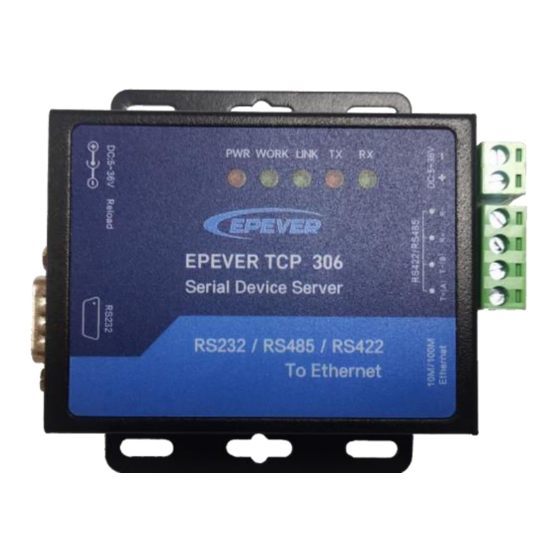
1 Overview EPEVER TCP 306 is a serial device server connecting with EPEVER solar controller, inverter, and inverter/charger via an RS485 port. Communicating by the TCP network, it transfers collected data to the EPEVER cloud server to realize the remote monitoring, parameter setting, and data analysis. -
Page 7: Pin Definition
❶ Port Instruction ❷ Power port Support 5V~36V DC power adapter ❸ Reload button Return to the factory settings ❹ RS232 interface Reserved Indicator To indicate the working status ❺ Power terminal Connect the solar controller, inverter, and (2P 5.08) inverter/charger for power supplying ❻... -
Page 8: Indicator
Definition for the RS422/ RS485 terminal: Instruction For the RS422, they are data transmitting pins to send data to the serial T+(A) device. T-(B) For the RS485, they are data transmitting and receiving pins. They are data-receiving pins for the RS422 communication. 1.1.2 Indicator Indicator Status... -
Page 9: Work On Epever Cloud
2 Work on EPEVER cloud 2.1 System connection Select an appropriate communication cable per the communication interface of the controller, inverter, or inverter/charger. 2.2 Work procedures Step 1 log in to the cloud server: Enter (https://hncloud.epsolarpv.com/) in Google browser to log in to the cloud server. - Page 10 Step 3 Add a gateway: Click "Gateway manage > Gateway list > Add" to enter the gateway adding interface. Input the gateway information and click the "Save" button. "Gateway SN" is obtained by scanning the QR code on the module sticker via the EPEVER cloud APP.
- Page 11 "Equipment Serial Number" can be obtained from the device sticker. "Gateway" must be the added gateway in Step 3. "Select Product Family" must be selected correctly, or it will cause a communication failure. Step 5 Set the IP type: There are two methods to obtain the IP address for the module. One is "Static IP,"...
- Page 12 "IP type" as "Static IP" or "DHCP." Step 6 System connection: Connect the EPEVER TCP 306 module to a router by a network cable, and connect the module to a controller, inverter, or inverter/charger by an RS485 cable.
- Page 13 Click the "User center page" to enter the power station list. Select a power station to enter its overview page. You can check the real-time status, historical curve, device information, alarms, etc., and set parameters.
-
Page 14: Work On Lan
3 Work on LAN 3.1 LAN connection Connect the TCP module to a PC by the Ethernet port, and connect the module to a controller, inverter, or inverter/charger by an RS485 cable. After successfully connecting to the PC, users can modify the TCP module's parameters or monitor the connected devices with the PC software. -
Page 15: Configure Tcp Module
2. Enter the "ipconfig" command in the pop-up window and press the "Enter" key to view the local IP address. 3. It is shown in the figure below: Local IP address: 192.168.20.24; Subnet mask: 255.255.255.0; Default Gateway: 192.168.20.1. 3.2.2 Configure TCP module 1. - Page 16 Note: The I P addr ess of the TCP modul e i s shown o n the modul e l abel . 3. Clic k to open the "EPEVER TCP RJ45 B.exe" tool , which can be requested from the after-sales technicians.
-
Page 17: Add Virtual Com
is 192.168.20.1. Change the value of the "Subnet Mask" and "Gateway" items to the same. (3)Change the "Module work mode" to "TCP Server." (4)Change the "Local Port" to "65010." After modifying the above parameters, click the "Save Config" button. 3.2.3 Add Virtual COM 1. -
Page 18: Monitor Devices With The Pc Software
TCP module's "Ethernet" port to the router by a network cable (The TCP module and the PC must share the same network). 2. Download the PC software "Charge Controller V1.95 Windows" from the EPEVER website: https://www.epever.com/support/softwares/. Install the PC software "Solar... - Page 19 3. Double-click the icon on the PC to open the "Solar Station MonitorV1.95" software. The initial interface is shown in the figure below. 4. Click the "System" menu to pop a "Station Information" box. Then click the "Controller" tab and select "COM7" for the "Port" item ("COM7" is the virtual COM set in chapter 3.2.3 Add Virtual COM).
- Page 20 ① ② ③ ④ After finishing all settings, click the "Add" button. 5. After adding the "COM7", it displays "COM7 (Doesn't exist or not yet set up)" in the left navigation window. Configure the "COM7" in the following procedures. (1)Click the "COM7 (Doesn't exist or not yet set up)" in the left navigation window. (2)Click the "Port Config"...
- Page 21 (5)Select the "COM7 "in the "Configuration" field, and click the "Update" button to finish. 6. Click the "Parameters" on the top menu bar to monitor the devices and modify related parameters.
-
Page 22: Specifications
4 Specifications Model EPEVER TCP 306 Work voltage 5V~36VDC Work current 116mA@ 5V; 53mA@ 12V Ethernet type RJ45, 10/100Mbps, cross-direct adaptive Support network protocol IP, TCP/UDP, ARP, ICMP, IPV4, HTTP Serial port baud rate 600bps~230.4Kbps Transmission mode TCP Server, TCP Client, UDP Server, UDP Client Transmission delay <10ms... -
Page 23: Appendix 1 Dimension
Appendix 1 Dimension Unit: mm Any changes without prior notice! Version number: V1.0... - Page 24 HUIZHOU EPEVER TECHNOLOGY CO., LTD. Tel: +86-752-3889706 E-mail: info@epever.com Website: www.epever.com...
Need help?
Do you have a question about the TCP 306 and is the answer not in the manual?
Questions and answers