Table of Contents
Advertisement
Quick Links
BEFORE BEGINNING YOUR INSTALLATION
Read through the instruction guide before getting started with the installation. Professional installation is recommended for
this product.
CONTENTS
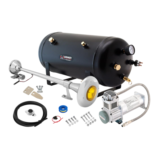
Single Trumpet Train Air Horn (Chrome Plated)
Detachable Weather Cover with Amber Light
200 PSI Air Compressor
5 Gallon Air Tank
12V Electric Air Valve (Solenoid)
240 PSI Air Pressure Gauge
170-200 PSI Pressure Switch
250 PSI Safety Valve
1/4" NPT Wing Style Drain Valve
1/4" NPT Compression Fitting for 3/8" OD Air Line
1/4" NPT Hex Head Male Plug
1/2" NPT Hex Head Male Plug x 2
3/8" OD Nylon Plastic Hose (10 Feet)
12mm Thread Sealant Tape (16 Feet)
30A In-line Fuse with Waterproof Holder
Remote Mount Air Filter
Horn Button
Mounting Hardware
The specific voltage requirement for this horn system is 12 volt DC, therefore installation must be done to a DC
power source of 12 volts.
SAFETY INSTRUCTIONS
Do not attempt to disassemble, repair or customize this product.
Avoid setting up any parts of this product where there is a risk of falling off or risk of coming in contact with water.
Avoid reaching out to touch or pick up any fallen or water submerged parts.
Never leave this product unattended during use.
Intended for use by adults only.
PAGE 1 of 7
VXO8350/1164Y
INSTALLATION GUIDE
Advertisement
Table of Contents

Subscribe to Our Youtube Channel
Related Manuals for Vixen Horns VXO8350/1164Y


Summary of Contents for Vixen Horns VXO8350/1164Y
- Page 1 VXO8350/1164Y INSTALLATION GUIDE BEFORE BEGINNING YOUR INSTALLATION Read through the instruction guide before getting started with the installation. Professional installation is recommended for this product. CONTENTS Single Trumpet Train Air Horn (Chrome Plated) Detachable Weather Cover with Amber Light ...
- Page 2 VXO8350/1164Y INSTALLATION GUIDE During and immediately after use, avoid touching any part of the compressor with bare hands as it is very hot during such periods. Avoid sounding the air horn when in close range to your ear(s) or the ear(s) of others.
- Page 3 VXO8350/1164Y INSTALLATION GUIDE COMPRESSOR MOUNTING Determine a dry place to mount your compressor. If you have chosen to install in the engine compartment, you should mount it as close to the front as possible to allow for maximum flow of air around compressor and also to avoid heat from the exhaust.
- Page 4 VXO8350/1164Y INSTALLATION GUIDE AIR TANK MOUNTING Find a convenient mounting location in your vehicle for the air tank. Ensure ports are reachable before drilling any holes. Mark the location of holes using the mounting brackets of the air tank as a template, and then drill to size.
- Page 5 VXO8350/1164Y INSTALLATION GUIDE ELECTRICAL CONNECTION COMPRESSOR The red wire of the compressor should be connected to (+) 12-volt power source. IMPORTANT: To prevent the compressor from over running and possible damage due to an air leak, connect the compressor’s red wire to a power source in the vehicle that only gets power when the vehicle’s ignition is on.
- Page 6 VXO8350/1164Y INSTALLATION GUIDE ELECTRICAL CONNECTIONS (LIGHT) OPTION 1: Additional Brake Light (Will turn on only when the vehicle's brake is engaged) Connect the red wire to any wire that powers the vehicle’s brake light. Connect the black wire to ground by wiring it to bare metal.
- Page 7 VXO8350/1164Y INSTALLATION GUIDE Issue: Excessive moisture in horn or safety valve. Solution 1: Depressurize and drain the tank. Solution 2: Relocate the compressor to a drier location. Issue: Continual cutting-off of Thermal overload protection. Solution 1: Relocate the compressor to a drier, cooler location.
Need help?
Do you have a question about the VXO8350/1164Y and is the answer not in the manual?
Questions and answers