Advertisement
Quick Links
Table of Contents
Description . . . . . . . . . . . . . . . . . . . . . . . . . . . . . . . . . . . . .1
Specifications . . . . . . . . . . . . . . . . . . . . . . . . . . . . . . . . . . .1
Regulatory Information . . . . . . . . . . . . . . . . . . . . . . . . . . . .1
Mounting the PSX-M8 Power Control Module . . . . . . . . . .1
PSX-M8 Power Control Module Overview . . . . . . . . . . . . . .2
Connecting the PSX-M8 Power Control Module . . . . . . . . .4
Input and Output Wiring . . . . . . . . . . . . . . . . . . . . . . . . . . .5
Programming . . . . . . . . . . . . . . . . . . . . . . . . . . . . . . . . . . .6
Application Example . . . . . . . . . . . . . . . . . . . . . . . . . . . . .10
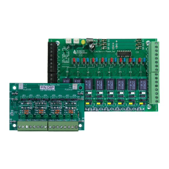
Description
The PSX-M8/M8P power control modules add 8 zones to an
PSX power supply system for powering and monitoring locks,
cameras, or other critical devices . The PSX-M8/M8P MUST be
used with an PSX-NL4 network module . The PSX-M8/M8P ac-
cepts either one or two voltage sources, either of which are se-
lectable for output on a zone-by-zone basis . Each input is fully
programmable via software to accept a voltage, dry contact, or
open collector input . Each zone output is selectable via soft-
ware for FAI operation, constant output, maglock output, or
fail-safe or fail-secure doorstrike outputs . The suffix "P" added
to the model number denotes Class 2 Power Limited outputs .
Specifications
Power Input
Voltage
Current
Standby Current
Zone Input
Voltage Input
Max Current
Zone Output
Voltage
PSX-M8
Current
PSX-M8P
Current
Fuse
3A
Size
PSX-M8/M8P
Weight
PSX-M8/M8P
12 or 24VDC nominal ±15%
12A maximum
300mA
All lock control relays active
12 or 24VDC
10mA
Same as input
3 .0A resistive
2 .5A resistive
(Class 2 Power Ltd)
ATM automotive style
(M8 only)
6 .00" x 4 .00" x 1 .4"
(152mm x 64mm x 36 mm)
0 .35lb (0 .16kg)
PSX-M8/M8P Installation Manual
Regulatory Information
The equipment discussed within this manual has been tested
to the following standards:
• UL294, UL603, UL1076
• ULC S318, ULC S319
• CSFM Approved
Mounting the PSX-M8 Power Control Module
Mounting of the board to an enclosure is via the four
snap-in standoffs supplied .
1 . Locate the appropriate mounting holes in the enclosure
and snap the standoffs into the holes .
2 . Align the board mounting holes with the standoffs (be
sure the PC board is properly oriented) and snap the
board onto the standoffs .
3 . Connections to the module shall be completed within
the same room, not exceeding a length of 100 ft .
Class 2 power limited wiring must be seperated from non-power limited wiring by
a minimum of 1/4 inch and must use seperate knockouts.
• The installation and all wiring methods shall be in accordance with ANSI/
NFPA70 and all local codes.
For ULC compliance, installation and all wiring methods shall be in accordance
with the Canadian Electrical Code, C22.1, Part I, Section 32 .
All input wiring to the module shall be located within the same room (90 ft).
P03-036 revAO1
Advertisement

Subscribe to Our Youtube Channel
Related Manuals for Tyco Security Products Software House PSX-M8

Summary of Contents for Tyco Security Products Software House PSX-M8
- Page 1 PSX-M8/M8P Installation Manual Table of Contents Regulatory Information Description . . . . . . . . . . . . . . . . . . . . . . . . . . . . . . . . . . . . .1 The equipment discussed within this manual has been tested to the following standards: Specifications .
- Page 2 PSX-M8/M8P Installation Manual PSX-M8 Power Control Module Overview INPUT FIELD WIRING 1-8 A B A B A B A B IN1 IN2 IN3 IN4 IN5 IN6 IN7 IN8 FlexIO FlexIO 1 2 3 Output Output Status Status BR B2 B1 FAULT...
- Page 3 PSX-M8/M8P Installation Manual Fault LED (FAULT) – Yellow B2 Connectors (J7 & J8) This LED lights when the PSX-M8/M8P detects a ruptured These fastons are for connection to the B2 voltage buss in the output fuse or other fault condition (including a tripped upper system .
- Page 4 PSX-M8/M8P Installation Manual Connecting the PSX-M8/M8P Power Control Module Remove all AC and battery power from the PSX system before adding or replacing a power control board. Each of the B1, B2, BR, and FlexIO busses has two connectors. These connectors may be used interchangeably. Required Connections For example: FlexIO from the power supply may be connected Optional Connections...
- Page 5 PSX-M8/M8P Installation Manual PSX-M8/M8P Input and Output Wiring INPUT WIRING INPUT FIELD WIRING 1-8 Each input on the PSX-M8/M8P has an “A” terminal and a “B” terminal . A B A B A B A B • When using a dry contact to activate the input, the con- tact is placed across these terminals .
- Page 6 PSX-M8/M8P Installation Manual PSX-M8/M8P Programming This section discusses software programming of the PSX-M8/M8P board . It assumes a basic understanding of the PSX-NL4 soft- ware GUI interface . Consult the PSX-NL4 manual (P03-037) for more information on using the PSX-NL4 interface . Accessing the PSX-M8/M8P from the PSX-NL4 interface Control Input - This column indicates the state of the input terminals for each zone as "Active"...
- Page 7 PSX-M8/M8P Installation Manual The PSX-M8/M8P Status Page...
- Page 8 PSX-M8/M8P Installation Manual The PSX-M8/M8P Programming Page input is activated . From the PSX-M8/M8P Status page of the PSX-NL4 inter- Fail-Safe Strike - The output power will be removed when face, click the "Programming" button near the top left cor- the input is activated .
- Page 9 PSX-M8/M8P Installation Manual The PSX-M8/M8P Programming Page...
- Page 10 PSX-M8/M8P Installation Manual PSX-M8 Application Example NO Contact Open Collector (Transistor) In NC Contact +12/24V Voltage IN No Connection A B A B A B A B IN1 IN2 IN3 IN4 IN5 IN6 IN7 IN8 INPUTS FlexIO 1 2 3 B2 12V B1 24V FAULT...
- Page 11 PSX-M8/M8P Installation Manual Zone 1 Zone 6 24V Mag Lock Output, Voltage Input 24V Door Holder Power, no control input This zone shows a typical 24V Mag Lock application, using This zone shows continuous 24V auxiliary power for pow- a voltage input on the zone . The door can be configured via ering devices such as door holders .
- Page 12 c o I n t e r n a t i o n a l C o m p a n y PSX-M8/M8P Installation Manual www.swhouse.com The trademarks, logos, and service marks displayed on this document are registered in the United States [or other countries]. Any misuse of the trademarks is strictly prohibited and Tyco International Ltd. will aggressively enforce its intellectual property rights to the fullest extent of the law, including pursuit of criminal prosecution wherever necessary.
Need help?
Do you have a question about the Software House PSX-M8 and is the answer not in the manual?
Questions and answers