Table of Contents
Advertisement
Quick Links
Advertisement
Table of Contents

Summary of Contents for Embention VERONTE AVIONICS STICK
- Page 1 Stick Embention Oct 31, 2022...
-
Page 3: Table Of Contents
CONTENTS 1 Introduction 2 Quick Start First Steps ..........2.1.1 Installation . - Page 5 Stick CONTENTS...
- Page 6 Stick CONTENTS...
-
Page 7: Introduction
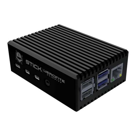
CHAPTER INTRODUCTION Fig. 1: Stick This document describes how to install and use the Veronte Stick Expander (VSE), including its technical specifications. VSE system is a single solution to generate sixteen channels PPM that can be used for flying with computer joystick. A simple web application allows the user to customize the number of channels and their output signals. - Page 8 Stick Chapter 1. Introduction...
-
Page 9: Quick Start
CHAPTER QUICK START 2.1 First Steps 2.1.1 Installation To open the VSE application it is necessary to follow these steps: 1. Connect the joysticks through the USB port. 2. Turn on the device and wait a few seconds. 3. Click the Network icon in the computer and connect the WiFi network named VSE-0XXX... - Page 10 Stick Fig. 1: Select WiFi network 4. Enter the wifi password: giy77uHQvOROoMoLEwKK 5. Once the network is connected, open the browser and go to the page http://192.168.16.1 Chapter 2. Quick Start...
-
Page 11: Warnings
Stick Fig. 2: Web Application 2.2 Warnings • Power Supply: Stresses above those listed in the power supply table (see supply) may cause permanent Power damage to the device. This is a stress rating only; functional operation of the device under these or any other conditions above those listed in the operational sections of this specification is not implied. - Page 12 Stick Chapter 2. Quick Start...
-
Page 13: Technical
CHAPTER THREE TECHNICAL 3.1 Features • 802.11 b/g/n/ac Wireless LAN • 1x SD Card • 2x USB2 ports • 2x USB3 ports • 1x PPM Connector 3.2 Mechanical Specifications Weight 280g Enclosure material Black anodized aluminium Dimensions 90x64.5x33mm... -
Page 14: Dimensions
Stick 3.2.1 Dimensions Fig. 1: Stick dimensions 3.3 Electrical Specifications 3.3.1 Power Supply USB-C input 5.0V Power Consumption 15W - 3A 3.3.2 I/O Specifications Input voltage/current • Power input: 5.0V up to 3A • Minimum: -0.5V • Maximum: 6.0V 3.3V Output Digital Input/Output (GPIO) •... -
Page 15: Interfaces
Stick • Current I (oh): 1.6mA and I (ol) = -1.6mA 3.4 Interfaces There is only one interface connection, with the following connectors: Fig. 2: Interface connection I/O Connections Number Connector Female 1x Power input Female 2x USB2 ports Female 2x USB3 ports Female 1x PPM... - Page 16 Stick Chapter 3. Technical...
-
Page 17: Hardware Installation
CHAPTER FOUR HARDWARE INSTALLATION 4.1 Mechanical installation The following diagram represents the basic mechanical installation of the VSE. Fig. 1: Mechanical installation... - Page 18 Stick Chapter 4. Hardware Installation...
-
Page 19: Software Installation
CHAPTER FIVE SOFTWARE INSTALLATION 5.1 Configuration This section explain in detail all the features of VSE Application. The software that allows the configuration of the channels. 5.1.1 Channels Once in the application, to configure the channels: 1. Click in Configuration. 2. - Page 20 Stick 3. Click Add Button It is possible to add N trim buttons related to an axis. Each button with different step offset. The offset can be positive or negative. This trim works as follows: With the indicated value in Increment (%), it is calculated the trim value on the current Stick Input value of the stick. Fig.
-
Page 21: Joystick Output View
Stick 5.1.2 Joystick Output View To make easier the channel’s configuration, the application shows the output values of every joystick connected. Fig. 4: Joystick View The buttons are represented with ON or OFF status and the axes with their values between [-1, 1]. 5.2 PPM Configuration in Pipe To properly use the VSE solution, it is important to configure the PPM entries in Veronte Autopilot using Veronte Pipe software. - Page 22 Stick Chapter 5. Software Installation...
-
Page 23: Operation
CHAPTER OPERATION 6.1 Download Configuration Data When the channels are saved, in the configuration page it is possible to view the schema. Also, this channel’s configuration can be downloaded. Fig. 1: Download Button 6.2 Upload Custom Configuration In the Configuration page, channels can be customized uploading a compatible file. Click on Upload Config button and drag the file into the input area. -
Page 24: Refresh Joysticks
Stick Fig. 2: Upload Modal 6.3 Refresh Joysticks After connecting or disconnecting any Joystick, it is recommended to click Refresh button to reload and re-read all Joysticks again. Fig. 3: Refresh Button Chapter 6. Operation... -
Page 25: Maintenance
CHAPTER SEVEN MAINTENANCE 7.1 Software Update The software version is updated using the executable program called updater.exe and the corresponding zip-folder with the new version. The customers will find these files in their FTP folder. • Open the Command Line (CMD) in the folder where is the updater.exe. •... - Page 26 Stick Chapter 7. Maintenance...
-
Page 27: Acronyms And Definitions
CHAPTER EIGHT ACRONYMS AND DEFINITIONS Command Line Ground GPIO General Purpose Input/Output Pulse Position Modulation Reception Transistor-Transistor Logic Transmission Universal Serial Bus Voltage Common Collector Veronte Stick Expander... - Page 28 Stick Chapter 8. Acronyms and Definitions...
-
Page 29: Contact Data
CHAPTER NINE CONTACT DATA You can contact Embention in any moment if you need further help and support from the acquired products. You can do that through email, telephone or by visiting our office. Embention contact data is as follows: Email: support@embention.com...
Need help?
Do you have a question about the VERONTE AVIONICS STICK and is the answer not in the manual?
Questions and answers