Advertisement
Table of Contents
- 1 LED Indicators, Wires, Auxiliary Input and Output
- 2 Components
- 3 Equipment Communication
- 4 RS485 Address Setting, Restore Factory Setting, Terminal Resistance Setting
- 5 TCP/IP Communication
- 6 RS485 Communication
- 7 Connection of Lock
- 8 “Wet Mode” Wiring Diagram of Lock Connecting with External Power Supply
- Download this manual
C3-400 Installation Guide
1.
Cautions
Please note the following cautions. Mis-operation may lead to personal injury or equipment failure:
1) Do not energize the system before installation is complete; never carry out installation activities when the system is energized.
2) All peripheral devices must be grounded.
3) It is preferred that all wires run through PVC or galvanized conduit.
4) It is strongly recommended that the length of the exposed part of any connection cable not be longer than 4 mm. Professional
clamping tools may be used to avoid unintentional contact of exposed wires to avoid short-circuit or communication failure.
5) It is recommended that card readers and buttons be installed at a height of 1.4m-1.5m above ground.
6) It is recommended to use the accompanying power supply for the control panel, and external power supply for each lock.
Description of normal working state:
Connect the system to the power supply. If the system works properly, the POWER indicator (red) is lit constantly and the RUN
indicator(green) flashes.
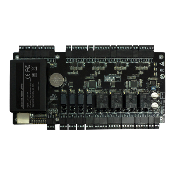
2.
Components
Key hole
Heat
dissipation
hole
Thread hole
Appearance of case
3.
Get through the thread hole
Thread hole
Get through the thread hole
Vision: 1.0.1
Date: Oct.
2010
Backup battery Power supply Control panel
2
1
Fixed case
4.
LED Indicators, Wires, Auxiliary Input and Output
Notes:
1) Meaning of LED indicators:
LINK indicator (green): always (green) indicates TCP/IP
communication is proper;
ACT indicator (yellow): flashing indicates data is transmitting
through TCP/IP communication.
TX indicator (yellow): flashing indicates it is sending data through
RX indicator (green): flashing indicates it is receiving data through
RS485 communication.
Auxiliary output indicator (green): always (green) indicates it is in use.
Lock indicator (green): always (green) indicates lock is open.
POWER indicator (red): always (red) indicates control panel power is on.
RUN indicator (green): flashing indicates the system works normally.
CARD indicator (yellow): flashing indicates card is punched on reader.
LINK
SD Card
Ethernet interface
ACT
Dip switch
Advanced Access Control
485+
PC RS485 interface
485-
GND
TX
RX
NO
D
COM
t1
Auxiliary outpu
NC
{
D
NO
COM
Auxiliary output2
NC
{
NO
D
COM
Auxiliary output3
NC
{
NO
D
COM
Auxiliary output4
NC
{
SEN
GND
C
NO
Door1
COM
NC
{
SEN
GND
C
Door2
NO
COM
NC
{
SEN
C
GND
Door3
NO
COM
NC
{
SEN
GND
C
NO
Door4
COM
NC
V+
A
Power to lock
V-
+12V
A
Power to control panel
GND
2) Recommended use of wires:
A Use 2-conductor power cord
B Use 6-conductor wire between Wiegand reader and control panel
(RVVP 6x0.5mm) (choose the appropriate cord for the interface
you connect, such as 6, 8, 10 cord)
C Use 4-conductor lock power cord (RVV 4x0.75mm)
D Use 2-conductor switch power cord (RVV 2*0.5mm)
3) The auxiliary input may be connected to infrared body detectors,
alarms, switches, etc.
4) The auxiliary output may be connected to door bells, alarms, etc.
D
IN
GND
Auxiliary input1
D
IN
Auxiliary input2
GND
D
IN
GND
Auxiliary input3
IN
D
GND
Auxiliary input4
+12V
Extended
GND
RS485 output
485-
TX
485+
RX
D
IN
#1 Door Button
GND
BEEP
GLED
B
WD1
#1 Door
WD0
W
iegand reader
GND
+12V
IN
D
#2 Door Button
GND
BEEP
GLED
B
WD1
WD0
#2 Door
Wiegand reader
GND
+12V
D
IN
#3 Door Button
GND
BEEP
GLED
B
WD1
#3 Door
WD0
Wiegand reader
GND
+12V
D
IN
#4 Door Button
GND
BEEP
GLED
B
WD1
#4 Door
WD0
Wiegand reader
GND
+12V
POWER
RUN CARD
Advertisement
Table of Contents

Related Manuals for Zksoftware C3-400

Summary of Contents for Zksoftware C3-400
- Page 1 LED Indicators, Wires, Auxiliary Input and Output Notes: C3-400 Installation Guide 1) Meaning of LED indicators: Vision: 1.0.1 2) Recommended use of wires: Date: Oct. LINK indicator (green): always (green) indicates TCP/IP communication is proper; A Use 2-conductor power cord...
- Page 2 Equipment Communication RS485 Address setting, Restore factory setting, Terminal resistance setting Set RS485 address through DIP switch: The background PC software is able to communicate with the system according to two protocols (RS485 and TCP/IP) for data exchange and 1) Places 1-6 on the DIP switch are for setting the number of control panels when communicating through RS485. It is adapted for binary remote management.
- Page 3 “Wet mode” wiring diagram of lock connecting with external power supply. 1 2 3 4 5 6 7 8...
Need help?
Do you have a question about the C3-400 and is the answer not in the manual?
Questions and answers