Sign In
Upload
Download
Table of Contents
Contents
Add to my manuals
Delete from my manuals
Share
URL of this page:
HTML Link:
Bookmark this page
Add
Manual will be automatically added to "My Manuals"
Print this page
×
Bookmark added
×
Added to my manuals
Manuals
Brands
PSG Manuals
Controller
HR Series
Operating instructions manual
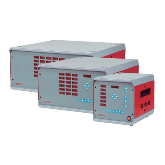
PSG HR Series Operating Instructions Manual
Hot runner controllers
Hide thumbs
1
Table Of Contents
2
3
4
5
6
7
8
9
10
11
12
13
14
15
16
17
18
19
20
21
22
23
24
25
26
27
28
29
30
31
32
33
34
35
36
page
of
36
Go
/
36
Contents
Table of Contents
Bookmarks
Table of Contents
Table of Contents
Brief Instructions HR/HRD
Overview HR/HRD
General Information
Safety Information
Operation
Basic Operating Information
Input Variants
Explanation of the Symbols for Operating Examples
Direct Selection of the most Important Functions Via Function Keys
The Zone Displays - Status and Error Messages
Target Value Input
Individual Input
Group-Block Input
Block Input Target Value Input All Zones at Once "Block
Selection Mode
Input Process at a Glance
Functions
Release Heating System
Manual
Automatically after Switching on
Switch off the Heating Outputs
Switching between the Actual Value and Control Difference Displays
Connecting Diagnosis (Only for the HR-D Series)
Alarm Acknowledgement
Monitoring Heating Currents
Target Current Specification
Automatic Current Acceptance
Manual Input of the Target Current Value
I- Acknowledge the Alarm
Leakage Current Display (Only for the HR-D Series)
Complete Leakage Current Display
Leakage Current Per Zone
Status Display
Process Control Function
Activation of the Process Control Function
Acknowledgement of the Process Alarm
Accepting New Process Parameters
Mold Check Function (Only for the HR-D Series)
Regulation Mode
Regulation Mode - Operation Via the Function Key
Recipe - Function
Save Recipe
Load Recipe
Delete Recipe
Lock Recipe
Standby
Boost
Acknowledge Alarm
Load Shedding
Pilot Zone Operating Mode
Select Pilot Zone
Regulation Ratio Amplification for Pilot Zone
Input Function Code
A Table of All Important Function Codes
Parameter Level
List of the Parameters Summarised below the Parameter Key
Function Descriptions HR/HRD Start-Up Mode
Start-Up Mode with Boost Function
Automatic Ramp Functions
Monitoring the Heating Current
Diagnosis Function "Allocation of the Sensors / Heating System
Self-Diagnosis
Diagnosis Sequence after Switching on
Version History
Advertisement
Quick Links
1
Table of Contents
2
Brief Instructions Hr/Hrd
3
General Information
4
Operation
5
The Zone Displays - Status and Error Messages
6
Manual
Download this manual
Operating Instructions
Hot Runner Controllers
Series
HR & HRD
from HRD Version 911006 A
HR Version 903905 A
PSG Plastic Service GmbH
Pirnaer Strasse 12-16
68309 Mannheim
Deutschland
Tel. +49 621 7162 0
Fax +49 621 7162 162
www.psg-online.de
Rev. 2.00.06
info@psg-online.de
03/2010
Table of
Contents
Previous
Page
Next
Page
1
2
3
4
5
Advertisement
Table of Contents
Need help?
Do you have a question about the HR Series and is the answer not in the manual?
Ask a question
Questions and answers
Related Manuals for PSG HR Series
Controller PSG HRD Series Operating Instructions Manual
Hot runner controllers (36 pages)
This manual is also suitable for:
Hrd series
Table of Contents
Save PDF
Print
Rename the bookmark
Delete bookmark?
Delete from my manuals?
Login
Sign In
OR
Sign in with Facebook
Sign in with Google
Upload manual
Upload from disk
Upload from URL


Need help?
Do you have a question about the HR Series and is the answer not in the manual?
Questions and answers