Table of Contents
Advertisement
Quick Links
Advertisement
Table of Contents

Related Manuals for Vzor MAPK-902

Summary of Contents for Vzor MAPK-902
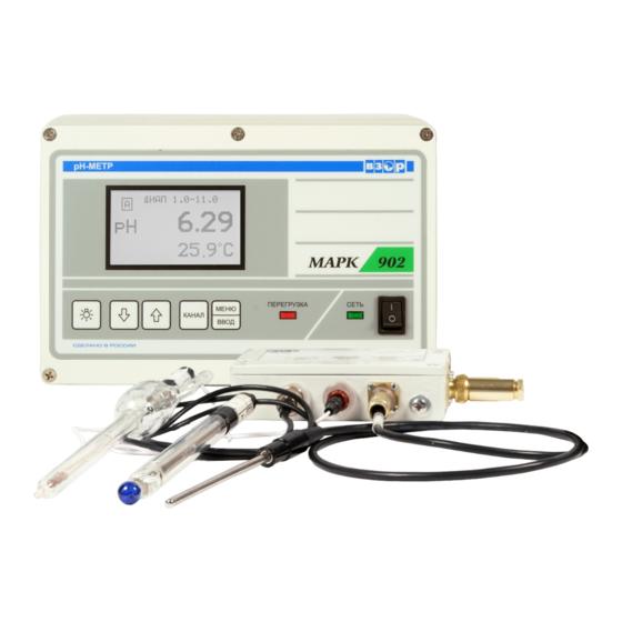
- Page 1 MAPK-902 pH-METER Operation Manual АЯ 74 Nizhny Novgorod 2010...
- Page 2 VZOR Ltd. will be grateful for any proposals and criticisms helping improve the product. If you have any trouble using the instrument please contact us in writing or by phone. Mailing address 603106 Nizhny Novgorod, P.O.B. 253 Telephone/fax (831) 229-65-30, 229-65-50...
-
Page 3: Table Of Contents
C O N T E N T S 1 DESCRIPTION AND OPERATION ............... 4 1.1 Purpose ......................4 1.2 Basic parameters and dimensions ..............5 1.3 Specifications ....................8 1.4 Product components ..................10 1.5 Design and operation ..................10 1.6 Measuring instruments, tools and accessories .......... -
Page 4: Description And Operation
1.1.2 The рН-meter is designed for continuous measuring of hydrogen ion activity index (pH) and aqueous solution temperature. 1.1.3 MAPK-902 and MAPK-902/1 рН-meters are intended to measure hy- drogen ion activity index (pH) in thermal power industry and various industries. -
Page 5: Basic Parameters And Dimensions
рН-meter ЭС-10601/7 ЭСр-10106-3.0 ЭСК-10617/7 Sensitive version glass reference combined element version electrode electrode glass electrode MAPK-902 − MAPK -902/1 flow-through/dip MAPK -902А − − MAPK -902А1 MAPK -902МP − − line-dip (LD) MAPK-902МP/1 1.1.6 This рН-meter version incorporates an electronic preamplifier galvanically isolated from the converter and located next to the electrodes to in- crease the allowable distance between the converter and the electrode system. - Page 6 1.2.5.1 Analyte medium (aqueous solutions) temperature, С ….. + 5 to + 50. 1.2.5.2 Analyte medium pressure MAPK-902А, MAPK-902А/1, MAPK-902LD, MAPK-902LD/1, MPа …………………………………..0 to 0.025. 1.2.6 Operating conditions 1.2.6.1 Ambient air temperature, С ……………………………….. + 5 to + 50.
- Page 7 Table1.4 pH-meter Component name and identification Overall Weight, version dimensions, mm, max MAPK-902 Converting unit ВР31.01.000 MAPK-902А 2.60 252146100 MAPK-902LD MAPK-902/1 Converting unit ВР43.01.000 MAPK-902А/1 2.60 26617095 MAPK-902LD/1 MAPK-902 PU-902 probe unit ВР31.02.000: MAPK-902/1 ВР31.02.100 amplifier unit; 1208330 0.05 ...
-
Page 8: Specifications
MAPK-902А, MAPK-902А/1, MAPK-902MP and MAPK-902MP/1 ver- sions ……………………………………………..………..……......± 0.20. 1.3.4 Margins of allowable complementary absolute error of the MAPK-902А, MAPK-902А/1, MAPK-902MP and MAPK-902MP/1 pH-meter versions in measur- ing рН caused by a change in the analyte medium pressure, ranging from 0 to 0.025 MPa, рН... - Page 9 1.3.20 рН-meter’s output signal (reading) settling time, min, maximum … 15. 1.3.21 Converter’s warm-up and heat balance settling time, h, max ……. 0.5. 1.3.22 If the measured рН or U value (for MAPK-902 and MAPK-902/1 ver- sions) or temperature goes beyond range limits, the audible alarm goes off and the OVERLOAD indicator lights up on the рН-meter face panel.
-
Page 10: Product Components
1.3.23 Any excess by the measured рН or U value (for MAPK-902 and MAPK-902/1 versions) of the threshold limits will cause the symbol to ap- pear on the рН-meter indicator screen and the threshold relay to operate. 1.3.24 When connected to a personal computer (PC), the рН-meter ex- changes information with PC through the RS-485 interface. - Page 11 nal (from 0 to 5 mA or from 4 to 20 mA) may be set separately for each channel. The lower (0 or 4 mA) and upper (5 or 20 mA) limits of a current output range cor- respond to the programmed pH measuring subrange start and end values (by cur- rent output).
- Page 12 1.5.3 pH-meter components 1.5.3.1 Converting unit The converting unit is a microprocessor instrument designed to display measuring results (рН, рН , U and temperature), generate a current output signal, control the threshold relay and exchange with a PC. The unit is powered from sin- gle-phase 220 V AC 50 Hz mains.
- Page 13 button “ ” to switch on and off the display screen illumination; “OVERLOAD” red LED indicator to show an overloaded range for current output, temperature and U; “POWER” green LED power on indicator. The panel-mounted CU rear panel (see Fig.1.2) and the wall-mounted CU lower panel (see Fig.1.3) feature the following components: ~220 V 50 Hz 10 V∙A 1.0 A...
- Page 14 two connectors “CHANNEL А” and “CHANNEL А” for cables connecting probe units and the converting unit; “CURRENT OUTPUT, SIGNALING, RS-485” connector to hook up re- cording and actuating equipment and to hook up the pH-meter to PC; terminal“ « ” to connect protective earthing to the pH-meter frame. The panel-mounted CU rear panel features the “~220 V 50 Hz 10 V∙A 1.0 A”...
- Page 15 Figure 1.4 PU-902 and PU-902А probe units Amplifier unit 1 has a sealed aluminum housing that features the connectors as shown in Fig.1.4. In the PU-902 probe unit the electrode system comprising measuring elec- trode 2 (рН-electrode) and reference electrode 3 is connected to the “INPUT 1” and “INPUT 2”...
- Page 16 Figure1.5 Housing 1 provides sealed protection for the amplifier unit board and contact joints. The probe unit electrode section (working parts of the combined electrode and temperature sensor) is protected by housing 2 representing a steel pipe holed to provide free circulation of analyzed water in the electrode area. Retention screw 8 prevents inadvertent unscrewing of housing 2.
- Page 17 Indicated on the screens are channel names (А or В), upper and lower limits of programmable measuring subrange values (by current output) and measured electrode system рН, рН , U and temperature values. Toggling among measuring channel indication modes is by successively pressing the “CHANNEL”...
- Page 18 MENU А В PASSWORD: SYSTEM ADDRESS: SOUND: CU TEMPERATURE: 38 С ►EXIT Figure 1.10 The required menu item is highlighted with the “►” marker moved up and down the screen with the “”/“” buttons. menu After the “►” marker is set at the required menu item, press the “ ”...
- Page 19 value, if necessary. Once all the digits and units of measurements are set (no number is flash- menu ing), use the “”/“” buttons to set the “►” marker at EXIT and press the “ ” enter button. 1.5.5.3 Using MENU [А] and MENU [В] screens (Fig. 1.11) MENU А...
- Page 20 pH values from 0.0 and 14.9 рН (with interval of 0.1 pН) may be set in the THRESHOLD MIN line and pH values from 0.1 and 15.0 pН (with interval of 0.1 pН) in the THRESHOLD MAX line. menu Once all the required values are set, press the “ ”...
- Page 21 menu To exit this screen, press the “ ” button. enter The pH-meter will change over to the MENU mode. ► MODE: рН a menu item meant to select the channel indication mode (рН, рН , U). To change the indication mode, set the “►” marker at this menu item. Each menu depression of the “...
- Page 22 If the password feature is off (“PASSWORD: OFF”), no password is request- ed for changeover from the measuring mode to the MENU mode. If the password feature is on (“PASSWORD: ON”), the pH-meter will request to enter the password (12) for changeover from the measuring mode to the MENU mode.
- Page 23 1.5.5.5 Warning and failure screens The warning screen as shown in А Fig. 1.17 will appear if the probe unit WARNING ! cable is not connected CHANNEL A or B, as appropriate. PROBE IS NOT CONNECTED ! Figure 1.17 The warning screen as shown in А...
- Page 24 The warning screen as shown in RANGE 8.0–10.5 В Fig. 1.20 will appear, if the measured pH value falls outside the set pH 10.94 measuring subrange (by current out- рН put). Set the correct pH measuring range (by current output). 25.0 °С...
-
Page 25: Measuring Instruments, Tools And Accessories
The warning screen as shown in RANGE 8.0–10.5 А Fig. 1.24 will appear, if the measured pH value goes beyond the lower 8.53 рН threshold limit. 24.3 С Figure 1.24 The warning screen as shown in RANGE 8.0–10.5 А Fig. 1.25 will appear, if the measured 8.53 pH value goes beyond: рН... -
Page 26: Intended Use
2.1.2 When using the pH-meter protect its electrodes and converting unit against impacts as they comprise glass components. 2.1.3 When using MAPK-902 and MAPK-902/1 versions for pH immersion measurement, ensure that electrodes are dipped in an analyte solution at least 16 mm deep, but no higher than the electrolyte level in the reference electrode. -
Page 27: Ph-Meter Setting-Up Procedures
2.3 pH-meter setting-up procedures 2.3.1 Receipt of рН-meter Before use, unpack the pH-meter, check the set for completeness and make sure the components are intact. If the pH-meter has stayed in cold environment, keep it at room temperature for at least 1 h before starting setting-up procedures. 2.3.2 Probe unit preparation 2.3.2.1 PU-902 probe unit preparation Prepare electrodes in accordance with their certificates. - Page 28 2 holes, 4.5 Figure 2.1 Layout of attachment holes for PU-902/PU-902А probe unit’s amplifier unit 2.3.2.2 PU-902LD probe unit preparation The PU-902LD probe unit comes complete with a combination electrode in- stalled therein. The electrode is protected with a cap. Before removing the cap, un- do retention screw 8 (Fig.1.5 а) and unscrew protective housing 2.
- Page 29 60-70 mm Coupling nut Pipe 57 mm 40-45 mm а Figure 2.2 2.3.3 Converting unit setting-up procedures 2.3.3.1 Converting unit installation Install the pH-meter so that the de-energizing of the conductivity meter is not hindered. The layout of attachment holes provided in the panel for a panel-mounted converting unit is shown in Fig.2.3.
- Page 30 2 holes 5.5 Figure 2.3 − Layout of attachment holes for a panel-mounted converting unit М5 screws with nuts included in the delivery set are used for attachment. The layout of holes for vertical attachment of a wall-mounted converting unit is shown in Fig.2.4.
- Page 31 Install the terminal block as appropriate. Attachment holes are shown in Fig.2.5. 2 holes 4 Figure 2.5 If connection requires that the cable is disconnected from the terminal block, proceed as follows after cabling: pass the cable through the sealed entry in the terminal block case; ...
- Page 32 Figure 2.6 2.3.4.1 Connection of external recording unit The external recording unit is connected to the converting unit through the “CURRENT OUTPUT, SIGNALING, RS-485” connector contacts, as per Table 2.1. Table 2.1 Contact No. Circuit Channel А (+) Channel В (+) Channel В...
- Page 33 2.3.4.3 Connection of external actuating and warning equipment Connection of external actuating and warning equipment to the converting unit is through the “CURRENT OUTPUT, SIGNALING, RS-485” connector con- tacts. If measured рН, рН , U and analyte medium temperature values exceed the specified limits, the relay’s dry contacts close the circuits between the РС19ТВ...
- Page 34 2.3.5 pH-meter parameter checkout and changing Proceed as follows: menu press the “ ” button, the pH-meter will switch over to the parameter enter checkout and changing mode (MENU [А] screen as shown in Fig. 1.2 will appear); check (or set) channel A parameters in accordance with 1.5.5; ...
- Page 35 Prior to calibration, check the temperature sensor of MAPK-902, MAPK-902А and MAPK-902/1 pH-meters for correct connection: ID numbers of the amplifier unit and temperature sensor must coincide. The reference electrode or combination electrode filling hole must be opened. Wash pH-electrodes and the PU-902/PU-902А probe unit temperature sen- sor or the PU-902LD probe unit operating section first in distilled water (in two ves- sels in succession) and then in the calibration buffer solution exhibiting pH = 1.65...
- Page 36 menu 4 Press the “ ” button, the screen as shown in Fig.2.9 will appear. enter CALIBRATION рН А AUTOMATIC MANUAL ►EXIT Figure 2.9 menu 5 Set the “►” marker at AUTOMATIC and press the “ ” button, the enter screen as shown in Fig.2.10 will be displayed showing the buffer solution pH value measured before calibration.
- Page 37 8 If the buffer solution pH value is not defined automatically, the screen as shown in Fig.2.12 will be displayed. In this case refer to Section 2.5 of this Opera- tion Manual (Troubleshooting. Table 2.5). CALIBRATION рН А CALIBRATION ERROR ! BUFFER IS NOT DEFINED ! Figure 2.12 9 If the buffer solution pH value is defined automatically, it will be displayed...
- Page 38 the PU-902/PU-902А probe unit temperature sensor or the PU-902LD probe unit operating section from the first buffer solution. Wash them in distilled water (in two vessels in succession) and then in a volume of the second buffer solution and place in the fresh second buffer solutions. Wait for the pH-meter readings to settle down.
- Page 39 ELECTRODE А = 100 % Ei = -35 рНi = 7.00 CHECK ELECTRODE ! ► EXIT Figure 2.17 If indicated values fall outside the permissible limits the blinking “CHECK ELECTRODE !” caption will come on in the display bottom line. Switch the pH- meter off and check the electrodes (integrity of electrodes and electrolyte level in the reference electrode).
- Page 40 menu 19 Use the “”/“” buttons to set the “►” marker at EXIT. Press the “ ” enter button to put the pH-meter into the measuring mode as shown, for example, in Fig.2.20. Range 1.0–11.0 А 9.22 рН 21.9 С Figure 2.20 Calibration is over.
- Page 41 menu 4 After the display settles down, press the “ ” button. The screen as enter shown in Fig.2.22 will appear, with the initial digit flashing. CALIBRATION А 09.16 рН 25.0 ˚С −165 mV ► ENTER VALUE Figure 2.22 5 Enter the pH-value of the calibration buffer solution, in accordance with menu 1.5.5.2.
-
Page 42: Measurements
meter will go into the MENU mode, having saved the previous calibration values. menu 8 Use the “”/“” buttons to set the “►” marker at EXIT. Press the “ ” enter button to put the pH-meter into the measuring mode as shown, for exam- ple, in Fig.2.24. -
Page 43: Troubleshooting
2.5 Troubleshooting Typical pH-meter failures and remedial actions are provided in Table 2.4. Table 2.4 Trouble Probable cause Remedy 1 рН-meter does not turn on Blown fuses Factory repair 2 Unstable рН-meter read- Open cable or loose Check and provide relia- ings contact in electrode ca- ble contact or remedy... - Page 44 2.5.1 Replacement of fuses Supply line fuses of a panel-mounted pH-meter may be replaced by the user. Supply line fuses of a wall-mounted pH-meter are to be replace on a factory basis after the faults which have destroyed fuses are cleared. Two ВП2Б-1В...
-
Page 45: Maintenance
3 MAINTENANCE 3.1 pH-meter scheduled maintenance 3.1.1 Periodic inspection of the converting unit, probe units and connecting cables for mechanical damage. 3.1.2 Periodic inspection of the flow reference electrode for a sufficient amount of КСl solution with a 3.0 М concentration. 3.1.3 Cleaning of dirty exterior CU surfaces with soft detergents. - Page 46 Cable seal nut Combination electrode retaining nut Washer Cable Sealing ring Washer Sealing ring Housing Reference electrode contact Amplifier Measuring unit board electrode contact Ring 043-047-25 Ring Combined Combined 042-048-36 electrode electrode retaining nut Probe unit electrode section а Shrink tube Shrink tube Shrink tube F32-1;...
- Page 47 Prepare the cable of a replacement combination electrode according to Fig.3.1 e. To this end, proceeds as follows: cut a length of cable of about 100 mm; desheath the cable over a length of 30 mm; put the shrink tube F32-1, L=25 ± 0.5 from the spare part kit onto the shield conductor running from the reference electrode and heat shrink it;...
-
Page 48: Delivery Set
4 DELIVERY SET 4.1 The delivery set is as shown in Table 4.1. Table 4.1 Description Code Quantity per version MAPK- 902 902/1 902А 902А/1 902МP 902МP/1 1 Converting unit ВР31.01.000 − − − ВР43.01.000 − − − 2 Probe unit: ВР31.02.000 −... -
Page 49: Appendix A. Ph Of Standard Buffer Solutions Versus Temperature
APPENDIX A (reference) pH of standard buffer solutions versus temperature Table А.1 Chemistry of buffer solutions 1.65 3.56 4.01 6.86 9.18 10.00 4.000 6.961 9.475 10.273 3.998 6.935 9.409 10.212 1.638 3.997 6.912 9.347 10.154 1.642 3.998 6.891 9.288 10.098 1.644 4.001 6.873... -
Page 50: Appendix B. Ph Of Highly Dilute Alkaline And Acid Solutions As
APPENDIX B (reference) pH of highly dilute alkaline and acid solutions as a function of the analyte medium temperature, computed using the data from MU 34-70-114-85 Guidelines 9,00 8,00 7,00 6,00 Temperature Температура... -
Page 51: Appendix C. Protocol Of Data Communications With Pc
Comment address code byte Test Read the type of net- work device Read RegIndChannel Read OfficialMaster Read OfficialMaster1 Read OfficialSlave KeyKod KeyKod depression simutation RegIndChannel Write RegIndChannel Type of network device: 1 – MAPK-302; 2 – MAPK-902; 3 – MAPK-408. - Page 52 Table C.2 − Channel 1 Pream- System Chan- Operation Lead data Trail data byte CRC Comment address code byte Channel A test CRC Read FirstWord_A and SecondWord_A Read U_A Read T_A Read pH_A Read pH25_A Read S_A Read Ei_A Read StartDiapA Read WidthDiapA Read MAX_A Read MIN_A...
- Page 53 Write RegIndChannel OfficialMaster Write OfficialMaster OfficialMaster Write OfficialMaster1 OfficialSlave Write OfficialSlave Type of network device: 1 – MAPK-302; 2 – MAPK-902; 3 – MAPK-408. Table C.5 − Channel 1 Pream- System Chan- Operation Lead data Trail data byte CRC Comment...
- Page 54 Table C.6 − Channel 2 Pream- System Chan- Operation Lead data Trail data byte Comment address code byte Response to chan- nel B test FirstWord_ SecondWord_В CRC Write FirstWord_В В SecondWord_В U_В_Hi U_В_Lo Write U_В T_В_Hi T_В_Lo Write T_В pH_В_Hi pH_В_Lo Write pH_В...
- Page 55 OfficialMaster – master processor status word GlobalErr_B GlobalErr_A Cal_B Cal_A Port Iout Iout (current output) – current output value: at 0 – 0-5 mА; at 1 – 4-20 mА; Port – port type: at 0 – RS-232C; at 1 – RS-485; Cal_A –...
- Page 56 RegWork – operating mode: 0 – pre-measurement normal operation; 1 – normal operation; 2 – status: рН calibration; 3 – status: temperature calibration; 4 – data package contains electrode parameter info; InCom – incorrect command: at 0 – command taken correctly; at 1 –...
Need help?
Do you have a question about the MAPK-902 and is the answer not in the manual?
Questions and answers