Advertisement
Device connection

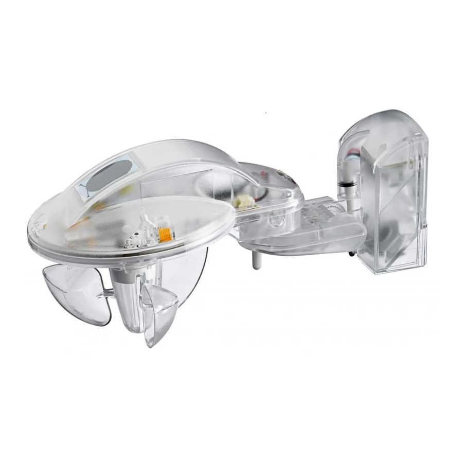
Device description


- Holder
- Hinged arm
- Temperature
- Wind speed
- Brightness sensor, right-hand side
Brightness sensor, centre
Brightness sensor, left-hand side - Rain sensor
- Wall holder with cable entry and terminals
- Horizontal installation
- Drilling pattern
The weather sensor 6190/11-102 measures the wind speed, rain, brightness (in three directions), temperature, and - via the GPS signal - also the date and time. The 6190/11-102 is adapted to the central weather station of BUSCH-JAEGER. An additional heating transformer is not required.
Location

Select an installation location at the building where the sensor can measure the wind, rain, and sun without hindrance. Ensure that there are no elements above the weather sensor from which water may drop onto the sensor after the rain or snow has stopped. Shadows of the building, trees, or adjacent buildings must not fall onto the weather sensor. There must be at least 60 cm of free space under the weather sensor in order to ensure a correct wind measurement and to prevent it from being snowed up. Magnetic fields, transmitters, and noise fields of power consumers (e.g. fluorescent lamps, neon signs, or switched-mode power supplies etc.) may disturb or even block the reception of the GPS signal. Please take this into consideration when planning the set-up. The GPS weather sensor must have a free view of the GPS satellite.
Technical sata (excerpt)
| Power supply | 24 V DC SELV |
| Current consumption | 200 mA |
| Connections | (0V potential) power supply(24V potential) power supply A/B (RS 485) serial datacommunication |
| Terminals | labelled, plug-in type |
| Line length | between the central weather station and the weather sensor 100m max. |
| Cable type/ cross-section | P-YCYM or J-Y(ST)Y, 2x2x0.8 |
| Power loss P | Max. 4.15 W |
| Temperature range operation (Tu) | -25...+60°C |
| Storage | -25...+60°C |
| Transport | -25...+70°C |
| Protection rating | IP44 in accordance with EN 60 529 |
| Protection class | II according to EN 61 140 |
| Overvoltage category | III according to EN 60 664-1 |
| Pollution degree | 2 according to EN 60 664-1 |
| Atmospheric pressure | Atmosphere up to 2,000 m |
| Installation | Wall/pole installation |
| Dimensions | 109 x 121 x 227 mm (H x W x D) |
| Wind speed (4) | Measuring range 0...24 m/s |
| Brightness (5) | Measuring range 0...100,000 lux |
| Rain (6) | During operation, the sensor surface becomes hot. |
| Temperature (3) | Measuring range -25...+60°C |
Under certain conditions, e.g. in the case of direct or adverse insolation, the temperature sensor may not work properly.
Connection
Pass the cable for the power supply and data communication through the rubber seal on the underside of the wall socket (6) and connect the voltage conductors (1/2) and data communication conductors (A/B) to the terminals provided for this purpose.
Close the housing by pushing the holder (1) downwards over the wall holder (7) from above. Then tighten the screw in the holder (1).
Installation notes
Ensure that it is correctly connected. The terminal designations are located on the wall holder (7). The device is ready for operation after connection of the mains voltage to the weather unit.
Installation
During installation, care must be taken to ensure that the temperature sensor (3) is not damaged. It may take a few minutes before reception is established after voltage is applied. The LED will stop flashing and go off 10 mins. after switch-on.
LED continuously on = voltage available
LED flashes = communication available
LED flashes 1x = compatibility mode
LED flashes 2x = new protocol
Installation of wall holder
The weather sensor with GPS receiver contains a wall holder (7). Fasten this vertically on the wall.
Fasten the wall holder (7) to the wall using the screws and washers provided. The washers are important in order to achieve protection rating IP 44.
Horizontal adjustment
There are T10 Torx screws on the bottom side of the hinged arm (2). If they are unscrewed by two turns, the hinged arm (2) is loosened and can be adjusted.
Important notes


Installation by person with electrotechnical expertise only. Please comply with all the relevant standards, guidelines, rules and regulations when planning and setting up electrical installations. Do not use the sensor in saline air. The rain sensor gets hot during the operation. There is a risk of burn when touching it. Do not touch the rain sensor.
- Protect the device against humidity, dirt, and damage during the transport and storage!
- Protect the device against dirt and damage during the operation!
- Comply with the technical data when using the device!
Cleaning
Soiled units can be cleaned with a dry cloth. If this is not sufficient, you can also use a cloth that is slightly impregnated with a soap solution. Do not use corrosive agents or solvents.
Maintenance
The weather sensor should be check for soiling regularly - at least twice per year - and cleaned if necessary. If the device is heavily soiled, the wind sensor may become inoperative, the device may permanently indicate rain, or it may not be able to detect sunshine. If the device is damaged (e.g. during the transport or stage), do not attempt to repair it.
Busch-Jaeger Elektro GmbH
Ein Unternehmen der ABB-Gruppe
Freisenbergstraße 2 D-58513 Lüdenscheid
Zentraler Vertriebsservice
Tel: +49 2351 956-1600
www.BUSCH-JAEGER.de

Documents / Resources
References
Download manual
Here you can download full pdf version of manual, it may contain additional safety instructions, warranty information, FCC rules, etc.
Advertisement


Need help?
Do you have a question about the 6190/11-102 and is the answer not in the manual?
Questions and answers