Table of Contents
Advertisement
Contents
Quick Start .................................................................... 2
Wiring Diagrams ...........................................back cover
AirPod™ Installation
Mounting the unit ................................................................3
Wiring . .......................................................................................3
Component Installation
Mounting compressor ........................................................4
Mounting tank . ......................................................................4
Mounting air valves .............................................................4
Mounting pressure sensors . ..............................................5
Wiring . .......................................................................................5
Installation Guide
& Operation Manual
Thank you for choosing a RideTech air suspension control
system. We are committed to providing the best experience
possible throughout the process of getting your car on air.
Our commitment doesn't end with your purchase, in fact,
it has only begun. This guide should provide you with the
information you need to properly install and set-up your
suspension control system.
However, if you find yourself having difficulty or if you have
a question that isn't covered in this book, please call our tech
department.
Tech Line: 812-481-4969
In addition to phone support, our web site also provides a
wealth of helpful product / install / set-up information.
LevelPRO Installation
Installing external ride height sensors . .........................6
Installing internal ride height sensors . ..........................6
Sensor Rod Assembly . .........................................................7
Example installations ..........................................................7
Button description ...............................................................8
Setting presets . ......................................................................8
Selecting presets . ..................................................................8
Tank button . ............................................................................8
Menu
Activating / navigating menu ..........................................9
Menu structure . .....................................................................9
Menu functions ............................................................10-11
Advertisement
Table of Contents

Related Manuals for Ridetech RidePRO e3

Summary of Contents for Ridetech RidePRO e3
-
Page 1: Table Of Contents
Installation Guide & Operation Manual Thank you for choosing a RideTech air suspension control system. We are committed to providing the best experience possible throughout the process of getting your car on air. Our commitment doesn’t end with your purchase, in fact, it has only begun. This guide should provide you with the information you need to properly install and set-up your suspension control system. However, if you find yourself having difficulty or if you have a question that isn’t covered in this book, please call our tech department. Tech Line: 812-481-4969 In addition to phone support, our web site also provides a wealth of helpful product / install / set-up information. -
Page 2: Quick Start
ARC4000e3 RidePro e3 4 way system / 3 gal. Tank APOD4100L 5 gal. Tank, 2 comp. LevelPro ARC4100L ARC4100e3 RidePro e3 4 way /dual comp. / 5 gal. Tank APOD4000L 3 gal. Tank, single comp. LevelPro LevelPro 4 way w/dual comp. / 5 gal. Tank ARC4700L LevelPro BIG RED 4 way / 5 gal. Tank ARC4700e3 RidePro e3 BIG RED 4 way / 5 gal. Tank APOD4100e3 5 gal. Tank, 2 comp. RidePro e3 ARC4800L LevelPro BIG RED MAX / two 5 gal. Tanks ARC4800e3 RidePro e3 BIG RED / two 5 gal. Tanks APOD4000e3 3 gal. Tank, single comp. RidePro e3 air pod LEV8000 LevelPro electronics package LEV8500 LevelPro upgrade for RidePro E3 LevelPRO™ and RidePRO e3® Systems differ only in the addition of the ride height sensors. -
Page 3: Mounting The Unit
Installing an AirPod AirPod Part #: APOD4000L APOD4000e3 APOD4100L APOD4100e3 STOP Remove the negative battery cable before beginning installation. MOUNT THE MAIN UNIT: 1- Mount the base flat to the vehicle surface (do not bend the base) 2- Secure the base with self tapping screws or bolts. 3 - Secure the cover to the airpod base using the supplied screws. CONNECT AIR LINES: 1 - Airline cuts must be straight and clean - use a razor blade or tubing cutter. (part # - cut1000) 2 - All fittings are DOT approved, reusable, push-to-connect style. Firmly push the airline into the fitting to attach. To release the airline push the collar on the fitting back towards the fitting and pull the airline out. 3 - All of our airlines are DOT approved so they are very strong. Secure the airline with zip ties, keep them away from any sharp edges and when passing through a hole in the frame use a grommet. -
Page 4: Mounting Compressor
Installing a RidePRO e3 System RidePRO e3 Part #: ARC4000e3 • ARC4100e3 • ARC4700e3 • ARC4800e3 LevelPRO Part #: ARC4000L • ARC4100L • ARC4700L • ARC4800L STOP Remove the negative battery cable before beginning installation. Mounting the Compressor Mounting the Air Tank • All of our compressors are sealed for moisture and dust resistance so they can... -
Page 5: Routing Air Lines & Fittings
• Use zip ties or other fasteners to secure the airline. Mounting the ECU (Electronic Control Unit) & Control Panel • The ECU is water proof and may be mounted in the engine bay or under the vehicle. • The control panel should be accessible from the drivers seat and may be mounted or left unmounted. • The control panel cable uses mini USB connectors. Extensions can usually be found locally or Power/Relay Air Pressure Valve Connector Connector Harness Connector purchased from RideTech. 0.460 3.816 0.460 2.477 3.816 Main Power Harness 2.477 Black wire A clean chassis ground Yellow wire Ignition 1.723... -
Page 6: Installing External Ride Height Sensors
Ride Height Sensors External LevelPRO Sensor Installation • T he LevelPro system uses 4 height sensors (one at each wheel). They are weather proof and may be mounted in any position as well as “clocked” in any position. (There is not a difference between the left and right sensors.) These sensors are typically mounted to the chassis / frame rail. • A linkage with rubber ends connects the sensor arm and a suspension component. On most front Attach to suspension suspensions the linkage will attach to the upper or lower control arm. On most rear suspensions it will attach to the axle or control arm. • The main goal when mounting the sensor is to achieve as much sensor rotation as possible without exceeding the sensors limits. • A lthough the sensor arm will rotate 180 degrees, it must remain in the middle 90 degrees throughout suspension travel. See diagram below for sensor travel limits. -
Page 7: Sensor Rod Assembly
Ride Height Sensors Assembly of the LevelPRO Sensor Link Rods 1- Once the linkage rod has been cut 2- Slide the heat shrink tubing over the 3- Heat the shrink tubing with a heat gun (hair to the proper length assemble the rubber end as far as it will go. dryer or small torch will work). linkage rod with heat shrink tubing Begin by heating the rubber end first. The and the rubber end. heat shrink is lined with adhesive and will stick to the rubber when heat is applied. 4- Continue shrinking the tube to the rod until 5- Once both sides of the linkage have been secured. Be sure not to overheat the tubing finished secure the linkage to the sensor causing it to pull from the rubber end. and suspension. Sensor Mounting Examples 69 Camaro Front Rear Trailing Arm 58-64 Impala Front... -
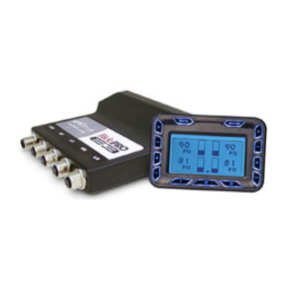
Page 8: Operation & Controls Button Description
Basic Operation & Controls Left Front Right Front Tank Menu INFLATE & DEFLATE BUTTONS Level Sensor Level Sensor Pressure Button Position Position You have full manual control at any time. To inflate an air spring simply press Left Front Right Front and hold the corresponding “+” button. To deflate an air spring simply press Air Pressure Air Pressure and hold the corresponding “-” button. The corresponding air spring will be inflated OR deflated until the button is released. Left Front Right Front Inflate Inflate Left Front Right Front Deflate... -
Page 9: Activating / Navigating Menu
Menu Options The main menu is used to change system parameters, such as increasing the brightness of the screen, or the menu is used to access system information, such as viewing your preset pressures and level sensor settings. To enter the Main Menu simply press the button. Main Menu Auto Leveling Dynamic Leveling Once in the menu you can scroll up using the button, scroll down Display Options System Setup Wireless Remote using the button, or select a menu item by pressing the SELECT DOWN button. You may go back a screen by scrolling to the bottom of each page and selecting the “BACK” button, or by pressing the button. MENU STRUCTURE MAIN MENU AUTO LEVEL DYNAMIC LEVELING DISPLAY OPTIONS... -
Page 10: Menu Functions
Menu Options - Details AUTO LEVEL DYNAMIC LEVELING: Dynamic Leveling will automatically raise or lower the vehicle back to the #2 The Auto Level on Start feature is used to raise the vehicle to the #2 Preset each Preset if the load changes while the vehicle is parked. As soon as the vehicle is time the ignition is turned on. in motion the system stops adjusting as it’s unsafe to alter air spring pressure while driving. ON: When vehicle is started it will return to the #2 Preset. ON: The vehicle will return to the #2 Preset if the load changes. OFF: When vehicle is started it will not automatically adjust to any setting OFF: The vehicle will not adjust if the load changes. DISPLAY OPTIONS Display Options allows you to change items such as the brightness of the screen or buttons as well as how long the screen will remain illuminated. OPTIONS TIME OUT FEATURE: KEYPAD INTENSITY: The display screen and button backlights can remain illuminated at all times, or The intensity of the button backlighting can be automatically adjusted if you wish they can turn off after some time. depending on ambient light conditions, or it can be changed to 3 intensity levels. OFF: The display will remain on as long as the ignition is on. 30 SECONDS: The display will remain illuminated for 30 seconds. AUTO: The backlight intensity will change with ambient light conditions. - Page 11 Menu Options - Details WIRELESS REMOTE LEARN KEYFOBS The E3 system has the capability of learning up to 4 remote keyfobs. Learning new keyfobs is as simple as pressing the #1 button on each keyfob, one at a time, until all keyfobs are learned into the system. Each new keyfob will be recognized by the E3 system and the corresponding number will be displayed on the screen. DOUBLE PRESET: If this feature is ON you will have to press the desired preset button on the keyfob twice in succession before the vehicle will travel to the desired preset. This feature is intended to minimize accidental triggering of a preset. TROUBLE SHOOTING The E3 system keeps a log of each error message that has been triggered. You may enter the Troubleshooting area of the menu for assistance in resolving any error. (errors are indicated by a on the main screen) Simply select the error you wish to resolve and the E3 system will walk you through the same steps our tech support staff uses to help you resolve the issue. ADVANCED OPTIONS The Advanced Options menu is a place where we keep tools and utilities to assist our staff in setting up or troubleshooting any area of the E3. The Advanced Options menu is accessible only with a pass code.
- Page 12 Wiring Diagram TANK MENU Shown with upgrade Storage Tank YELLOW SWITCHED +12VDC (IGNITION) +12VDC BLACK-TO CHASSIS OR BATTERY GROUND BLUE +12VDC GREY Primary Compressor Air Pressure Sensors A B T BLACK +12VDC Secondary Compressor BLACK Rear: Blue - Left Inflate Black - Right Inflate Pink...
Need help?
Do you have a question about the RidePRO e3 and is the answer not in the manual?
Questions and answers