
Related Manuals for VEMS V3MS DASH7

Summary of Contents for VEMS V3MS DASH7
- Page 1 VEMS ECUs Digital Dashboard for standalone ECUs VEMS V3.x QUICK GUIDE For model: HW22/12560N7P 3rd revision 12/2022...
-
Page 2: Table Of Contents
Content 1. Introduction a. Main parts of display unit 2. Electrical connection a. Display unit i. Power connector – PWR ( 6 pins ) ii. Control connector – CNTRL ( 7 pins ) b. Main Unit i. Main unit connector c. -
Page 3: Introduction
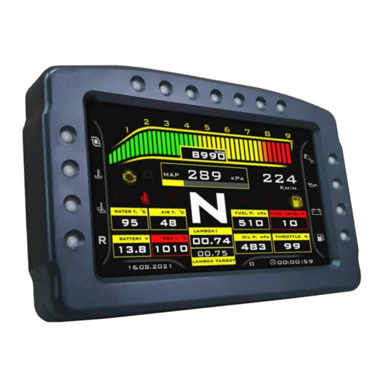
Introduction Main parts of display unit: 1. Body 2. 7inch TFT screen 3. Shift-light LED diodes 4. Warning LED diodes 5. Micro SD Card slot 6. Power connector 7. Control buttons connector 8. CR1220 Clock Battery cover 9. Mounting terminals 4x M5... -
Page 4: Electrical Connection
Electrical connection Display unit PWR connector ( 6 pins ) This connector is for power supply and communication between main unit and display unit. Without this connector connected, Dash7 won‘t work. This connector is wired from factory and this pinout is only for troubleshoting purposes. -
Page 5: Main Unit
Since firmware V7.3.3 and GUI V3.6.2KN Configurable input can be used as Digital Input for Neutral switch (in this case, connecting to GND means >> Neutral is selected) Pin C5: VEMS Serial RS232 data (ECU pin EC18/14) Pin C6: VEMS Serial RS232 data (ECU pin EC18/15) Pin C7: PWR connector of display unit –... -
Page 6: Base Connection Of Dash7
3. connect 6pin connector from main unit to the display unit. 4. plug in Dash7 RS232 cable to the RS232 connector of your VEMS ECU (NOT THE CONNECTOR NAMED LCD!) 5. connect BLACK WIRE from pin C8 of main connector to the vehicle GROUND or battery NEGATIVE terminal 6. -
Page 7: Full Connection Of Dash7
WARNINGS AND NOTES: NEVER DISCONNECT ANY CONNECTOR FROM DASH7 WHEN POWER SUPPLY IS ON ! ALWAYS USE 3 Amp (max 5 Amp) fuse for +12V power supply of Dash7 ! Locate fuse as close as possible to the main switch (or ignition switch). MAKE SURE YOUR GROUNDING IS PROPERLY CONNECTED ! MAKE SURE ALL CONNECTORS ARE CONNECTED PROPERLY AND LOCKED. - Page 8 Pressure sensor (3 wires version): Pin C2: Input signal from pressure sensor (0-5V) Pin A1: +5V sensors power supply (use Pin A8 for Sn2106 or older) Pin A3: Sensors GND NOTE: If your sensor has only 2 wires (usually resistance pressure sensors), connect one wire to the GND (pin A3), another wire to analog input (pin C2) and use pull-up resistor between +5V (pin A1) and the signal (pin C2).
- Page 9 Any 0-5V sensor (Configurable input pin): This input can be used with many types of sensors. For example: Pressure, Temperature, Position,...etc, with 0-5V output. Or can be used like a digital input for NEUTRAL GEAR SWITCH (since firmware V7.3.3 and GUI V3.6.2KN). Pin C4: Configurable Input –...
-
Page 10: Digital Inputs Switched To Ground
Digital inputs for displaying the vehicle lights status (+12V digital inputs) Pin B1: Input 4 (Low Beam lights +12V) Pin B2: Input 5 (High Beam lights +12V) Pin B3: Input 6 (Turn signal light LEFT SIDE +12V) Pin B4: Input 7 (Turn signal light RIGHT SIDE +12V) Pin B5: Input 8 (Reversing lights +12V) Connect wires directly from positive terminals of the bulbs to the Main unit connector. -
Page 11: Controls
Controls Quick Access functions Main controls of display can be reached also while driving (racing) by QUICK ACCESS. For reaching quick access functions you can use control buttons on remote controller. NOTE: Please, pay full attention to driving the vehicle and use quick access functions only at the safe places on a race track ! Quick Acces functions only change parameters, but do not save their values to the memory. -
Page 12: Graphic User Interface
Graphic User Interface (GUI) Dash7 has unique Graphic User Interface. GUI consists of Startup page with customised logo, Connection page, menu pages and 5 fully customised data pages. Data pages and Startup page can be completely customised. You can download templates or create your own design in our V3MS Web Dash Designer. You can use your own logo (picture or short video) at the Startup page . -
Page 13: Sd Card Full-Datalogger
SD Card Full-datalogger: If Dash7 was ordered with Full-datalogger, you can save essential data from the ECU to the SD Card during driving. For start logging only put your SD Card to the slot on a Main unit and set the action when log should start in the “DATA LOG“... -
Page 14: Mounting And Maintenance
(exhaust, heating, etc.). Do not expose to temperatures above 75 ° C (167 ° F) - Pay attention to the length of the wiring from Main unit to Display Unit and to the Vems ECU - Ideal location for the main unit is in a horizontal position, but can also be mounted vertically or "upside down"... -
Page 15: Maintenance
IMPROPER CONNECTION MAY DAMAGE OR COMPLETELY DESTROY YOUR V3MS Dash7 !!! - AFTER DOUBLE CHECKING you can turn ON the ignition (or other switch which turns ON the Dash7). VEMS ECU should be powered up before of together with Dash7. Otherwise, the connection to the ECU may not be successful. -
Page 16: Troubleshooting
Dash7 and the ECU or there is no data coming from the ECU. Check connection between Dash7 Main unit and VEMS ECU (RS232 connector) and check if the ECU is powered ON. Check if your ECU is not “PASSWORD PROTECTED”. If yes, disable password protection (or ask your tuner), because with password protection activated the ECU do not send out any data in Triggerframe protocol. - Page 17 13. When I connect a laptop to the ECU and disconnect a Dash7, it stops to display data. Can I have connected both, PC and Dash7 to the ECU at the same time? : Yes, you can have connected your laptop to the Vems ECU, and at the same time you can watch all data (from ECU and also from Dash7 inputs) on the Dash7, but you must to use an adapter “Tuning cable”...
- Page 18 17. Speed 1 or Speed 2 gauge still shows 0 kmh or mph even if car moves: You probably don't have a wheel speed sensor connected to the wheel speed input of the Vems ECU, or the sensor is not properly calibrated or faulty or installed incorrectly.
-
Page 19: Warranty
Warranty Factory standard limited warranty is 24 months from the date of delivery. Warranty covers manufacturing defects and damages created during production or packaging. Warranty does not cover the damage of the device by over-current, over-heating, over-voltage, under-voltage of the device and its inputs, also does not cover any mechanical or electrical damages made by consumer or third parties, or by natural disasters, damages caused by water or other liquids entering the device (device and it’s accessories are not waterproof or water resistant!), damages made by improper installation, extreme...
Need help?
Do you have a question about the V3MS DASH7 and is the answer not in the manual?
Questions and answers