
Subscribe to Our Youtube Channel
Related Manuals for Amada ML-5120A EU


Summary of Contents for Amada ML-5120A EU
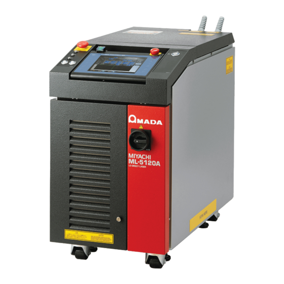
- Page 1 Original instructions DIRECT DIODE LASER ML-5120A OPERATION MANUAL AA04OM1183539-21...
-
Page 2: How To Use This Document
How to Use This Document Thank you for purchasing our Direct Diode Laser ML-5120A. This operation manual explains its method of operation and precautions for use. Before using, read this operation manual carefully; after reading, save it in a proper place for your future reference. -
Page 3: Table Of Contents
Contents How to Use This Document ..........2 For Use in Safety . - Page 4 Operating Part Chapter 1 Control Method, and Start and Stop . . . . . . . . . . . . . . . . . . . . . 59 1.
- Page 5 Chapter 3 Laser Processing by Laser Controller (PANEL CONTROL) . . 125 1. Operation Flow ........... .125 2.
- Page 6 Appendixes Specifications ............193 Dimensional Outline Drawings .
-
Page 7: For Use In Safety
For Use in Safety For Use in Safety Safety Precautions Before using, read "Safety Precautions" carefully to understand the correct method of use . These precautions are shown for safe use of our products and for prevention of dam- age or injury to operators or others. Be sure to read each of them, since all of them are important for safety. - Page 8 For Use in Safety WARNING Wear protective glasses . Be sure to wear protective glasses having an optical density of at least 7 while using the Laser. Even if you wear them, you may lose your sight if the laser beam enters your eyes directly through protective glasses. Protective glasses attenuates the laser beam, but does not block it.
- Page 9 For Use in Safety CAUTION Do not splash water on the Laser . Water splashed over the electric parts, can cause electric shock and short circuits. Use proper tools (wire strippers, pressure wire connectors, etc .) for termination of the connecting cables . Do not cut the wire conductor.
-
Page 10: Precautions For Handling
Precautions for Handling Precautions for Handling Laser Safety Supervisor ⇒ Appoint a safety supervisor for all laser work. The appointed safety supervisor must have sufficient knowledge and experience regarding both lasers and laser work. ⇒ The supervisor must control the keyswitch of the Laser, and must be responsible for instructing operators in safety aspects of the Laser as well as directing the laser work. - Page 11 Precautions for Handling factory. ⇒ When a supervisor or operator enters the area where the laser is used, protective measures not to exceed the MPE* level must be taken. * MPE: The maximum level of permissible exposure of the eyes or skin to laser beams. Abbreviation of Maximum Permissible Exposure.
-
Page 12: For Transportation
Precautions for Handling For Transportation When transporting the laser, observe the following precautions to avoid haz- ards . ⇒ Package the Laser when transporting it. ⇒ The worker must wear a helmet, safety shoes and gloves for safety. (Leather gloves are recommended.) ⇒... -
Page 13: For Packaging
Precautions for Handling Precautions for transportation ⇒ Transport it using a dedicated package to prevent a fall, damage due to vibration. ⇒ Retract the level adjuster fully when freighting the Laser. For Packaging Precautions for packaging ⇒ The worker must wear a helmet, safety shoes and gloves for safety. (Leather gloves are recommended.) ⇒... - Page 14 Precautions for Handling Packaging overview and name of each section Operating Procedure (1) Prepare the bottom cap and the base. ⇒ To avoid bending the base (the slope part), put laminated cardboard blocks (2 posiitons) at the bottom of the slope part with the hook and loop fastener. Bottom cap Base (2) Slowly put the equipment on the base from the slope part.
- Page 15 Precautions for Handling (3) Remove two laminated cardboard blocks after putting the equipment in place. Laminated cardboard Hook and loop block fastener (4) Stand the slope straight up and secure the corners of the bottom cap with joint clips. ML-5120A...
- Page 16 Precautions for Handling (5) Put the removed laminated cardboard blocks in place with the hook and loop fastener. (6) Put the cushion for cable storage on the top of the equipment and store the opti- cal fiber in it. Cushion for cable storage ML-5120A...
- Page 17 Precautions for Handling (7) Put front left, front right, rear left, and rear right cushions at the corners of the equipment. ⇒ You may install an external packaging sleeve in Step (8) first and insert cushions. Rear left cushion Front left cushion Front right cushion Rear right cushion (8) Install an external packaging sleeve.
-
Page 18: For Disposal
Precautions for Handling (9) Install the top cap. Top cap Bands For Disposal This product incorporates parts containing gallium arsenide (GaAs). At the time of disposal, separate it from general industrial waste or domestic waste and carry out the disposal in accordance with applicable laws and regulations. ML-5120A... -
Page 19: Sticking Warning/Danger Labels
DEFEATED AVOID EYE OR SKIN EXPOSURE TO DIRECT DEFEATED AVOID EYE OR SKIN EXPOSURE TO DIRECT OR SCATTERED RADIATION OR SCATTERED RADIATION (10) MANUFACTURED BY: AMADA WELD TECH CO.,LTD. 95-3 FUTATSUKA NODA-CITY CHIBA 278-0016 JAPAN MODEL No. SERIAL No. LABEL MFG:MONTH , YEAR 注意... - Page 20 DEFEATED AVOID EYE OR SKIN EXPOSURE TO DIRECT OR SCATTERED RADIATION 可視レーザ放射 MANUFACTURED BY: VISIBLE LASER RADIATION AMADA WELD TECH CO.,LTD. ビームをのぞき込まないこと。また、光学器具で直接ビームを見ないこと。 95-3 FUTATSUKA NODA-CITY DO NOT STARE INTO THE BEAM OR VIEW DIRECTLY WITH OPTICAL INSTRUMENTS CLASS 2M LASER PRODUCT CHIBA 278-0016 JAPAN 最大出力...
-
Page 21: Cautions For Export
Cautions for Export Cautions for Export The product described in this Operation Manual falls into a controlled item specified in the Foreign Exchange and Foreign Trade Law. When exporting the product from Japan, you need approval based on the said law. For details, please visit the Security Export Control’s website or contact the Security Export Licensing Division, Ministry of Economy, Trade and Industry directly. -
Page 25: Introduction Part
1 . Direct Diode Laser Chapter 1 Introduction Part ● Overview of the Direct Diode Laser 1 . Direct Diode Laser Laser means the equipment to generate powerful light by amplifying light (electromagnetic wave) or means this light itself. In direct diode laser, diode laser (LD) can be applied to the heat processing directly without passing through a crystaline body such as YAG and YVO The laser wavelength generated in this laser equipment is 915 nm of near infrared... -
Page 26: Mechanism Of The Direct Diode Laser
2 . Mechanism of the Direct Diode Laser 2 . Mechanism of the Direct Diode Laser The direct diode laser consists of a power supply, light source, optical fiber, output unit, etc. Laser light can be transferred to a place remote from the main unit by optical fiber, so that only the optical fiber and output unit can be mounted in the manufacturing line for processing. -
Page 27: Functions Of The Ml-5120A
3 . Functions of the ML-5120A 3 . Functions of the ML-5120A ⇒ Direct diode laser oscillation function ■ The laser is capable of processing workpieces under a small spot diameter. ■ The single laser provides CW and pulse output. ■... -
Page 28: Product Composition
4 . Product Composition 4 . Product Composition Packaging The main unit and accessories are packed together. The dimensions and mass are as follows. Dimensions Mass (including packaged products) Approx. 1100 (H) × 600 (W) × 1155 (D) mm Approx. 100 kg Checking the Packaged Products Make sure that all the packaged products are included. - Page 29 4 . Product Composition Main unit Output unit Optical fiber Main unit Provided with a safety shutter with open-close sensor and beamsplitter(s) according to the sharing specification. Model Sharing method Specification ML-5120A-010 Single delivery Output to a single fiber ML-5120A-020 2-powersharing Simultaneous output to 2 fibers Optical fiber...
- Page 30 4 . Product Composition *1: When the optical fiber is used in combination with the output unit FOCH-30B series, 20-m fiber cannot be used. Output unit The output unit with the specification that you selected at the time of purchase is con- nected to the main unit.
-
Page 31: Options
4 . Product Composition Options The following goods are options separately sold. Purchase them as required. Part name Model No . AS1162937 Touch panel extension cable 10 m AS1162938 15 m AS1162940 RS-232C/RS-485 conversion adapter MSC-08S AC adapter for RS-232C/RS-485 conversion adapter Exclusively for MSC-08 AS1155931 RS-485 cable... - Page 32 4 . Product Composition RS-232C/RS-485 Conversion Adapter This conversion adapter is used to control equipment by external communication. Output signals (RS-232C) of the personal computer are converted into RS-485 sig- nals and then output to the main unit. RS-485 cable RS-485 connector of the main unit RS-232C/RS-485 conversion adapter...
-
Page 33: Chapter 2 Name And Functions Of Each Section
1 . Name and Function of Each Section on the Front Side Chapter 2 Introduction Part ● Name and Functions of Each Section 1 . Name and Function of Each Section on the Front Side Front Cover Section This section explains each section of the front cover of the main unit . Function of Each Section on the Front Cover (1) MAIN POWER Switch Turns ON and OFF the power supply. -
Page 34: Inside Of The Front Side
1 . Name and Function of Each Section on the Front Side Inside of the Front Side The front door is opened to perform maintenance . Each section of the inside is explained below . Function of Each Section inside the Front Side (1) Filter Fixing Unscrewed to remove the air filter. -
Page 35: Name And Function Of Each Section On The Top Side
2 . Name and Function of Each Section on the Top Side 2 . Name and Function of Each Section on the Top Side Top Cover Section This section explains each section of the top cover of the main unit . POWER SHUTTER1 SHUTTER2... -
Page 36: Laser Controller (Mle-122A)
2 . Name and Function of Each Section on the Top Side (5) POWER Lamp When the MAIN POWER switch is turned ON, the POWER lamp comes on so that the operator can check that the power supply has been turned ON. (6) SHUTTER Lamp Stay(s) on while some (one) of the branch units 1 to 2 are (is) open. - Page 37 2 . Name and Function of Each Section on the Top Side (2) EMERGENCY This is an emergency stop button. With this button pressed, the laser STOP equipment operation is stopped. When the pressed button is turned in (Button) the direction of RESET (clockwise), the button is reset to the initial state. This button functions in the same way as the EMERGENCY STOP button of the main unit.
-
Page 38: Name And Function Of Each Section On The Rear Side
3 . Name and Function of Each Section on the Rear Side 3 . Name and Function of Each Section on the Rear Side This section explains each section on the rear side . (With the connectror cover removed) (12) (13) (14) (15) - Page 39 3 . Name and Function of Each Section on the Rear Side (9) REM . I/L Con- Connect it to the Remote Interlock for emergency stop. When this connector is closed, the safety shutter of the laser equipment nector are closed to shut off the laser light output. (10) PWRMON Con- BNC connector used to output an analog signal representing the monitor waveform of laser power.
-
Page 43: Installation And Preparation Part
1 . Installation Place Chapter 1 Installation and Preparation Part ● Installation This chapter explains where to install the laser equipment, and how to fix it. ⇒ At installation of this laser equipment, our engineer will take charge of adjust- ments. -
Page 44: Space Required For Installation
1 . Installation Place Space Required for Installation In the installation place of this product, a space is required in the surroundings. Install the product in a place remote from the wall as shown in the following figure. ⇒ Air flows in the direction of the red arrow shown in the following figure. Install the product so as not to interrupt the air flow. -
Page 45: Fixing The Laser Equipment
2 . Fixing the Laser Equipment ⇒ When a sudden temperature change occurs, for example, at a start of heat- ing, condensation will be caused to the surface of the lens or the mirror, thereby sticking dust there. Avoid such a sudden temperature change if possible. When there is a possibility of condensation, turn ON the power supply of the laser. - Page 46 2 . Fixing the Laser Equipment (2) Fix each adjuster on the floor by using a connecting apparatus such as anchor. Adjuster pressure (Fixing hole to floor) fixtures (74 .5) Lock nut Fix on floor Adjuster using anchor bolt 19 .5 Floor ⇒...
-
Page 47: Cooler Unit (Option)
3 . Cooler Unit (Option) 3 . Cooler Unit (Option) Select the model with the optional cooler unit when the Laser is used in conditions of high power and high temperature. When using the model with the cooler unit, pay attention to the following. Power Supply Voltage CAUTION The model with the cooler unit shall be used with the power supply voltage of 200 V... -
Page 49: Chapter 2 Connections And Preparations Of Each Section
1 . Connecting the Power Supply Chapter 2 Installation and Preparation Part ● Connections and Preparations of Each Section 1 . Connecting the Power Supply CAUTION Your qualified electrician must carry out the electrical connection to main power supply . (Also follow your local accident prevention regulations, such as the German Regulation, BGVA2 .) CAUTION For the power supply side, we earnestly recommend using a leakage breaker with... -
Page 50: Connecting The Optical Fiber
2 . Connecting the Optical Fiber 2 . Connecting the Optical Fiber This section explains the method of connecting the optical fiber on the laser beam output unit side . WARNING ■ Be sure to receive education for this work from our engineer . ■... - Page 51 2 . Connecting the Optical Fiber (3) Turn the outer-side nut of the plug in the direction of the arrow to fix the optical fiber. ⇒ Tighten the nut by hand without using a tool. ⇒ The connector section cannot be bent. Take care not to give excessive force to this section.
-
Page 52: Removing The Laser Controller
3 . Removing the Laser Controller 3 . Removing the Laser Controller For using the laser equipment in the status where the laser controller is separated from the main unit, remove the laser controller from the main unit. CAUTION Be sure to turn OFF the power supply before removing the laser controller . Operating Procedure (1) Hold the handle located in front of the laser controller and lift it up with holding down its rear portion to remove it. -
Page 53: Connecting The External Communication Conversion Adapter (Option)
4 . Connecting the External Communication Conversion Adapter (Option) 4 . Connecting the External Communication Conversion Adapter (Option) To perform laser processing by external communication control (RS-485 CONTROL) by using a control unit mounting RS-232C such as personal computer, the optional conversion adapter for external communication "RS-232C/RS-485 conversion adopt- er"... -
Page 54: Connecting The Cable For The Heat Detector (Option)
5 . Connecting the Cable for the Heat Detector (Option) 5 . Connecting the Cable for the Heat Detector (Option) To use the output unit FOCH-30B series, connect the cable for the heat detector at- tached to the output unit. Item required Cable for the heat detector Operating Procedure... - Page 55 5 . Connecting the Cable for the Heat Detector (Option) (4) While the KEY SWITCH CHECK screen is displayed, press the “INITIALIZE” but- ton and the right button (red portion in the above figure) of the laser controller simultaneously. The INITIALIZE screen appears. ⇒...
-
Page 59: Operating Part
1 . Control Method Chapter 1 Operating Part ● Control Method, and Start and Stop 1 . Control Method This section explains the control method for the laser . The following 3 control methods are available, namely, control from the laser control- ler (PANEL CONTROL), control by external input/output signals connecting the PLC (*) to the laser (EXTERNAL CONTROL), and control by sending commands from the personal computer or the like (RS-485 CONTROL). -
Page 60: Start And Stop
2 . Start and Stop Control by External Communication Control (RS-485 CONTROL) The control by external communication control is selected by sending a command to set the control method from the personal computer or the like connected to the main unit. -
Page 61: Chapter 2 Various Settings
1 . Setting Welding Schedules Chapter 2 Operating Part ● Various Settings 1. Screen Configuration This section explains the method of setting various laser processing schedules by using the laser controller . The set schedules can be protected so that they cannot be changed . - Page 62 1 . Setting Welding Schedules How to Use the Touch Panel The laser controller of this laser equipment adopts a touch panel type that permits touching the screen directly for an operation. Press the displayed button portion on the screen with a finger to select a screen or perform each setting. The colors of the setting buttons displayed on the basic screens are deep blue, black, light blue, and blue.
- Page 63 1 . Setting Welding Schedules Items and Buttons Common to Each Screen The display items, setting buttons, and screen selecting buttons provided on the following screens are common to the 4 types of basic screen. Display items and setting buttons Screen selecting buttons Display items and...
- Page 64 1 . Setting Welding Schedules How to Use the Screen Selecting Buttons SCHED When this button is pressed, the SCHEDULE screen appears. Select this button to set laser output conditions or call the set SCHEDULE. When this button is pressed, the MONITOR screen appears. Select this button to check the measured value of laser light.
-
Page 65: Checking The Equipment Status
2 . Checking the Equipment Status 2 . Checking the Equipment Status STATUS Screen On the STATUS screen, the laser control method, the laser light sharing specification, and the total number of laser light outputs can be checked. In addition, the error log, event log, and software version can be checked. -
Page 66: Setting The Output Status
2 . Checking the Equipment Status VERSION Displays the SOFTWARE VERSION screen. Then, the version of each soft- ware is displayed. ⇒ For the common items in the upper/lower part of the screen, refer to page 63. Setting the Output Status In the following, the method of setting the STATUS screen is explained . - Page 67 2 . Checking the Equipment Status Control by External Communication Control (RS-485 CONTROL) When a command to set a control method is sent from the personal computer con- nected to the main unit, external communication control is selected and "RS-485 CONTROL"...
-
Page 68: Terminal Monitor Screen
2 . Checking the Equipment Status TERMINAL MONITOR Screen When the Ext.I/O button is pressed on the STATUS screen, the TERMINAL MONI- TOR screen appears. On this screen, the external input/output is monitored. EXT . I/O (1) EXT . I/O (2) ML-5120A... - Page 69 2 . Checking the Equipment Status EXT . I/O (2) (AHC external I/O (option)) How to see the displayed items : Settable item INPUT Displays the current status of external inputs. OUTPUT Displays the current status of external outputs. EXT .I/O (1) Moves to the EXT.
-
Page 70: Ld Status Screen
2 . Checking the Equipment Status LD STATUS Screen When the POWER STAT. button is pressed on the STATUS screen, the LD STATUS screen appears. On this screen, the LD status such as serial number, temperature and deterioration rate is displayed. How to see the displayed items : Settable item LD UNIT... -
Page 71: Deterioration Check
2 . Checking the Equipment Status Deterioration Check It is recommended to do the deterioration check (Refresh) regularly to check the LD status. When the detected output is 90% or less of the that before shipping (Factory initial), error No.045/FC-LD POWER DOWN occurs. Press the TROUBLE RESET button to clear the error. -
Page 72: Error Log Screen
2 . Checking the Equipment Status ERROR LOG Screen When the ERROR LOG button is pressed on the STATUS screen, the ERROR LOG screen appears. On this screen, up to a thousand error histories are displayed in chronological order. When the number of histories exceeds a thousand, the histories beginning with the chronologically oldest history are overwritten. -
Page 73: Event Log Screen
2 . Checking the Equipment Status EVENT LOG Screen When the EVENT LOG button is pressed on the STATUS screen, the EVENT LOG screen appears. On this screen, up to four thousand operation histories are dis- played in chronological order. When the number of histories exceeds four thousand, the histories beginning with the chronologically oldest history are overwritten. -
Page 74: Software Version Screen
2 . Checking the Equipment Status SOFTWARE VERSION Screen When the VERSION button is pressed on the STATUS screen, the SOFTWARE VER- SION screen appears. On this screen, the version of each software is displayed. How to see the displayed items : Settable item Unit name Displays the name of unit which uses the software. -
Page 75: Changing The Equipment Settings
3 . Changing the Equipment Settings 3 . Changing the Equipment Settings CONFIG Screen On the CONFIG screen, the settings for equipment can be configured. The communi- cation settings, password, and displayed language can be changed while the equip- ment is running. How to see the displayed items : Settable item LASER... - Page 76 3 . Changing the Equipment Settings LASER CONTROL OPTION PARAMETERS How to see the displayed items : Settable item LD AUTO Sets the automatic start of the LD power supply to ON or OFF. At ON, the LD power supply becomes ON automatically and the screen is displayed in the status of LD: START NG LASER At ON, a laser stops when error No.035/LASER POWER OUT OF RANGE occurs.
- Page 77 3 . Changing the Equipment Settings RS-485 COMMUNICATION SETUP How to see the displayed items : Settable item NETWORK Sets the equipment No. in the range of #0 to #15 to perform remote operations by using the external communication function. BAUD Sets the communication speed from 9600, 19200, 38400, 57600, or 115200 bps.
- Page 78 3 . Changing the Equipment Settings TCP/IP COMMUNICATION SETUP How to see the displayed items : Settable item ETHERNET Displays the Ethernet address. ADDRESS Sets the IP address. ADDRESS SUBNET Sets the subnet mask. MASK DEFAULT Sets the default gateway address. GATEWAY Returns to the CONFIG screen.
-
Page 79: Password Screen
3 . Changing the Equipment Settings PASSWORD Screen On the PASSWORD screen, a password is set to protect the set processing sched- ule. When the password is set and validated, set values are protected and cannot be changed by any person other than the supervisor. How to see the displayed items : Settable item SCHEDULE... - Page 80 3 . Changing the Equipment Settings (3) Enter the set password into the password input box. Press the password by pressing keyboard keys on the screen. The AC key de- letes all the entered characters. The BS key deletes a character in front of the cursor one by one.
- Page 81 3 . Changing the Equipment Settings Validating the Password (1) Press the “SCHEDULE EDIT” button. When “LOCK” is selected on the window, the display on the button changes to “LOCK.” The password is validated and a part of setting items is protected, dis- abling a change.
- Page 82 3 . Changing the Equipment Settings (4) Press the ENTER key on the keyboard. A confirmation screen appears. ⇒ Unless 4 alphanumerical characters are not entered, an error message appears. Enter the password once again. (5) Enter the same password into the password re-input box (lower portion) and press the ENTER key.
- Page 83 3 . Changing the Equipment Settings Display Screen Item SCHEDULE Screen SLOPE (Time for down-sloping to the last FLASH) POINT 01 to 20 (Output time and output value of each point for FLEX) REPEAT (Number of laser light outputs per second) SHOT (Total number of laser light outputs) Fn (Schedule editorial assistant function) MODULATION screen:...
- Page 84 3 . Changing the Equipment Settings SETTING AT DATE AND TIME How to see the displayed items : Settable item DATE Sets year (last two digits), month and day. TIME Sets time in a 24-hour period. Returns to the CONFIG screen. ML-5120A...
- Page 85 3 . Changing the Equipment Settings HEAT DETECTOR SETTING Standard AHC external I/O (option) How to see the displayed items : Settable item DEVICE INFO . F/W VERSION The firmware version of the heat detector is displayed. MEASURING The measuring range of the heat detector is displayed. Generally, the range is RANGE wider than the rating.
- Page 86 3 . Changing the Equipment Settings OFFSET Sets the deviation of the measured temperature in the range of -50.0 to 50.0. The initial value is 0.0. Moves in parallel with the full measurement range. Also, linearly corresponds to the temperature indicated value. CURT .TEMP .
-
Page 87: Initialize Screen
3 . Changing the Equipment Settings INITIALIZE Screen On the INITIALIZE screen, the settings can be initialized, and the screen for setting such as the error output and the LD deterioration check is displayed. How to see the displayed items : Settable item INIT . - Page 88 3 . Changing the Equipment Settings USER SETTING How to see the displayed items : Settable item Ext .I/O "MONITOR TROU- Sets the output timing of the monitor upper/lower limit check error in the CW waveform. BLE" OUTPUT TIMING SCH. OUTPUT END: Output when output ends (default) (CW) MON.
- Page 89 3 . Changing the Equipment Settings Displaying the INITIALIZE Screen (1) Turn OFF the CONTROL keyswitch and turn ON the MAIN POWER switch. Power is supplied and the POWER lamp comes on. LASER EMERGENCY STOP START/STOP (2) While the KEY SWITCH CHECK screen is displayed, press the "INITIALIZE" but- ton and the right button (red portion in the above figure) of the laser controller simultaneously.
-
Page 90: Setting The Laser Light Output Schedule
4 . Setting the Laser Light Output Schedule 4 . Setting the Laser Light Output Schedule On the SCHEDULE screen, the laser light output schedules are set and registered by giving SCHEDULE numbers. If a registered SCHEDULE number is entered, the corresponding output schedules can be called. - Page 91 4 . Setting the Laser Light Output Schedule Sets the down-sloping (the laser output becomes gradually weaker) for the last SLOPE FLASH. Sets this time in the range of SLOPE ≤ FLASH1, FLASH2, FLASH3. REFERENCE The forecast value of laser output energy (J) based on the set laser output VALUE schedules is displayed.
-
Page 92: Schedule Screen (Flexible Waveform (Flex))
4 . Setting the Laser Light Output Schedule <No tes> - The laser output value (%) setting range is 0 to 200% . However, the laser output value cannot be set exceeding the maximum value of "PEAK POWER" x 100% . If the laser output value is set to 100%, the value set in "PEAK POWER"... - Page 93 4 . Setting the Laser Light Output Schedule RESOL When this button is pressed, the selected setting resolution can be set from 0.01 ms or 0.05 ms. When the setting resolution is changed, the currently-selected schedule is cleared and the initial value is set. MODU When this button is pressed, the modulation setting screen for the selected schedule number opens.
-
Page 94: Schedule Screen (Flexible Waveform (Cw))
4 . Setting the Laser Light Output Schedule SCHEDULE Screen (Flexible Waveform (CW)) How to see the displayed items : Settable item PEAK POWER Sets the peak value of laser output (value when "POWER" are 100%). Regarding the actual laser output value ("POWER"), set the ratio (%) to the peak value sup- posing that the set peak value is the reference value (100%). -
Page 95: Setting Laser Light Output Schedules
4 . Setting the Laser Light Output Schedule Setting Laser Light Output Schedules This section explains the how to set the SCHEDULE screen (fixed waveform (FIX)) . ⇒ 256 types of output schedules can be set and registered with SCHEDULE num- bers of #0 to #255. - Page 96 4 . Setting the Laser Light Output Schedule (5) Press the laser output time "TIME [ms]" and laser output value "POWER [%]" setting buttons of "FLASH1" to "FLASH3." Enter each value by using the numeric keypad and then press the ENT key. ⇒...
- Page 97 4 . Setting the Laser Light Output Schedule Setting ON/OFF for the Modulation Function (1) Press the "MODU" button to display the MODULATION screen. (2) Move the cursor to "MODU" and press the ON or OFF key to set whether the modulation function is valid or not.
- Page 98 4 . Setting the Laser Light Output Schedule Enabling/disabling the Active Heat Control Function (Op- tion) (1) Press the “HEAT” button to display the ACTIVE HEAT CONTROL screen. (2) Press the “MODE” setting button of “STAGE 01” to “STAGE 02” to set the control method of each stage of waveform.
- Page 99 4 . Setting the Laser Light Output Schedule (2) Check the output energy displayed in "REFERENCE VALUE." ⇒ In "REFERENCE VALUE", the forecast value of laser output energy based on the set output schedules is displayed. This value is a little different from the actually measured value (measured value displayed on the MONITOR screen) provided at laser processing.
-
Page 100: Seam Screen
4 . Setting the Laser Light Output Schedule SEAM Screen On the SEAM screen, the fade-in/out function of seam processing is set. The fade-in/ out function means a laser output value adjusting function. This function lowers and raises the later energy in a gentle slope form to provide a continuous waveform suit- able for seam processing. -
Page 101: Setting The Output Schedules For Seam Processing
4 . Setting the Laser Light Output Schedule Setting the Output Schedules for Seam Processing The method of setting the output waveform for seam processing by using the fade-in/out function after displaying the SEAM screen is explained below . ⇒ Only in the FIX or FLEX mode, the waveform for seam processing can be set. - Page 102 4 . Setting the Laser Light Output Schedule <No te> If the output count set in "SHOT" is smaller than that set in "SHOT [count]", any larger output count set in "SHOT [count]" is invalidated . When the output count set in "SHOT" is larger than that set in "SHOT [count]", the POWER of the final set value in "SHOT [count]"...
-
Page 103: Modulation Screen
4 . Setting the Laser Light Output Schedule MODULATION Screen On the MODULATION screen, the laser light modulation degree and the modulation frequency are set. Rectangular wave (RECT) Triangular wave (TRI) Sinusoidal wave (SINE) How to see the displayed items : Settable item DUTY Sets the duty ratio of the laser output value. - Page 104 4 . Setting the Laser Light Output Schedule MODULATION Sets the modulation degree of the laser output value. Sets the modulation width whose center is the laser output peak value (100% output value) in the range of 0 to 100% as a percentage of power. <Note>...
-
Page 105: Setting The Modulated Waveform
4 . Setting the Laser Light Output Schedule Setting the Modulated Waveform The method of setting the modulated waveform after displaying the MODULA- TION screen is explained below . ⇒ When using the modulated waveform, normally set the laser output value "POW- ER [%]"... - Page 106 4 . Setting the Laser Light Output Schedule Modulation = 40% 120 W 100 W (4) Press the "FREQUENCY" setting button. Enter the repetition frequency by using the numeric keypad and then press the ENT key. Enabling the Modulation Function (1) Press the "MODU"...
-
Page 107: Active Heat Control Screen
4 . Setting the Laser Light Output Schedule ACTIVE HEAT CONTROL Screen On the ACTIVE HEAT CONTROL screen, the active heat control function (option) is set. The active heat control function detects the temperature of the processing part and stops laser when it exceeds the target temperature. Standard AHC external I/O (option) - Page 108 4 . Setting the Laser Light Output Schedule Returns to the SCHEDULE screen. ⇒ For the common items in the upper/lower part of the screen, refer to page 63. EXPERT SETTINGS How to see the displayed items : Settable item CORRECTION Sets the correction factor in the range of 0.05 to 1.00.
-
Page 109: Setting The Active Heat Control Function (Option)
4 . Setting the Laser Light Output Schedule Setting the Active Heat Control Function (Option) The method of setting the active heat control function after displaying the AC- TIVE HEAT CONTROL screen is explained below . ⇒ For powersharings, the active heat control can be performed for only one deliv- ery. - Page 110 4 . Setting the Laser Light Output Schedule STAGE 01 Control method (SKIP, KEEP) In the stage set to SKIP, the operation proceeds to the next stage when the detec- tion temperature is “TARGET TEMP.” setting or higher or the laser outputs for the set time.
- Page 111 4 . Setting the Laser Light Output Schedule When SKIP or KEEP is set, the active heat control function set on the ACTIVE HEAT CONTROL screen is enabled. ⇒ When this function is not used, set it to "-." (3) Press the “TARGET TEMP.” button. Enter the target temperature in the rated range of the heat detector by using the numeric keypad and then press the ENT key.
- Page 112 4 . Setting the Laser Light Output Schedule Making the Daily Check The correction factor of soldering iron measured with a contact-type temperature is recorded before shipping. We recommend that you carry out a periodic check as fol- lows. (1) Set the “LD” setting button to OFF and the “BEAM” and “GUIDE” setting buttons to ON, and then adjust the position of guide light so that it falls on the following position.
-
Page 113: Editorial Assistant Function
4 . Setting the Laser Light Output Schedule Editorial Assistant Function When the “Fn” button is pressed on the SCHEDULE screen, a schedule can be initialized (RESET), copied (COPY) or pasted (PASTE). There is a beffer on a memory for storing a schedule data. With copy and paste functions, you can transfer a schedule data to or from the buffer. -
Page 114: Limitations Of Schedule Setting
4 . Setting the Laser Light Output Schedule Limitations of Schedule Setting Set schedules so as to satisfy following ranges. FIX/FLEX PEAK POWER 0 to 120 W REPEAT 1 to 5000 pps ― SHOT 1 to 9999 (9999 is for endless output.) ― 0.1ms resolution: 0.0 to 500.0 ms 1s resolution: 0 to 9999 sec 0.01ms resolution: 0, 0.05 to 99.95 ms... -
Page 115: Monitoring Output
5 . Monitoring Output 5 . Monitoring Output MONITOR Screen On the MONITOR screen, the measured value of monitored laser light is checked and the monitor value range is set. FIX / FLEX How to see the displayed items : Settable item ENERGY Displays the measured value (J) of laser energy. - Page 116 5 . Monitoring Output SHOT COUNT Displays the total number of laser light outputs. To reset the display to 0, perform a reset operation on the STATUS screen. GOOD COUNT Displays the appropriate number of laser light outputs. The appropriate number of outputs means the laser light output within the allowable energy range set at "HIGH"...
-
Page 117: Setting The Output Status Check Screen
5 . Monitoring Output Setting the Output Status Check Screen In the following, the method of setting the MONITOR screen is explained . Checking the Measured Energy Value of Laser Light When laser light is output, the MONITOR screen is automatically displayed and a measured energy value is displayed. - Page 118 5 . Monitoring Output Monitored waveform Controlled waveform - When the waveform is set with less than 1 ms of pulse width, the average power displayed in "AVERAGE" may differ from the actual laser output power. - When the set time exceeds 100 seconds in the CW waveform, the waveform shows trends in the past 100 seconds .
- Page 119 5 . Monitoring Output ⇒ When the total laser output time is higher than 0.5 s in the CW mode, set “HIGH” and “LOW” at the ratio of output (PEAK POWER × POWER [%]) set on the SCHEDULE screen. The following formula is given to convert the set value into Watts.
-
Page 120: Setting The Laser Light Delivery
6 . Setting the Laser Light Delivery 6 . Setting the Laser Light Delivery This laser can output single laser light to multiple optical fibers by the functions of the built-in beamsplitter. This section explains the sharing specifications of this laser . Laser Light Sharing The laser light sharing specification is divided into single and powersharing. -
Page 121: Operating Safety Shutters On Each Screen
6 . Setting the Laser Light Delivery Operating Safety Shutters on Each Screen In the following, the method of performing open/close operations for safety shutters on each screen . Perform open/close operations for safety shutters to transfer laser light. Operating Procedure (1) Press the "BEAM"... -
Page 122: Changing The Acceptance Time For Laser Start Signal/Schedule Signal (Config Screen)
7 . Changing the Acceptance Time for Laser Start Signal/Schedule Signal 7 . Changing the Acceptance Time for Laser Start Signal/ Schedule Signal (CONFIG Screen) This section explains how to change the acceptance time for the laser start sig- nal and schedule signal to be input into the EXT . I/O (1) and (2) connectors by setting the CONFIG screen when EXTERNAL CONTROL is exerted by external input/output signals . - Page 123 7 . Changing the Acceptance Time for Laser Start Signal/Schedule Signal Changing the Acceptance Time (1) Set the "LASER START DELAY." (2) Press the "X" button. The CONFIG screen reappears and the acceptance time for laser start signal and schedule signal is changed. ML-5120A...
-
Page 125: Chapter 3 Laser Processing By Laser Controller (Panel Control)
1 . Operation Flow Chapter 3 Operating Part ● Laser Processing by Laser Con- troller (PANEL CONTROL) 1 . Operation Flow This section explains a laser processing operation flow by laser controller. The following methods for laser processing operations are available: control from the laser controller (PANEL CONTROL), control by external input/output signals from the connected PLC (Programmable Logic Controller) (EXTERNAL CONTROL), and con- trol by sending a command from the connected personal computer (RS-485 CON-... -
Page 126: Laser Controller Functions
2 . Laser Controller Functions 2 . Laser Controller Functions This section explains the functions of the laser controller . At PANEL CONTROL, processing schedules are set by using the liquid crystal display of the laser controller and laser light is output by pressing the LASER START/STOP button. -
Page 127: Operating Procedure
3 . Operating Procedure 3 . Operating Procedure This section explains the operating procedure for laser processing to be con- trolled from the laser controller . ⇒ For the details of processing schedule settings, refer to Chapter 2, "4. Setting the Laser Light Output Schedule"... - Page 128 3 . Operating Procedure (2) Turn ON the CONTROL keyswitch. The power monitor is automatically checked. The SCHEDULE screen appears. Setting Output Schedules As an example, the procedure for setting SCHEDULE No.5, laser output peak value 50 W, FLASH1 laser output time 30 ms/output value 50%, and up-slope 10 ms is ex- plained below.
- Page 129 3 . Operating Procedure <Note> The settable value of laser output peak value is 0 to 120 W . For the laser output value setting (% of FLASH), set a value not exceeding the maximum value . For the laser output value setting (% of FLASH), set a value within the setting range . (4) Press the "TIME [ms]"...
- Page 130 3 . Operating Procedure Outputting Laser Light WARNING Be sure to put on specified protective glasses during laser light output operation. Even if you wear them, you may lose your sight if the laser beam enters your eyes directly through protective glasses . (1) Press the "STATUS"...
- Page 131 3 . Operating Procedure (6) Press the "CLOSE" button. The window is closed. ⇒ For the recommended method of using the safety shutter, refer to “Precautions for Handling” on page 10. (7) Press the "GUIDE" setting button to set it to ON to output guide light. The "GUIDE"...
- Page 132 3 . Operating Procedure Stopping Laser Processing CAUTION During a laser light output or for 5 seconds immediately after a laser light output, do not turn OFF the MAIN POWER switch . (1) Press the "LD", "BEAM" and "GUIDE" setting buttons on each screen to set them to OFF.
-
Page 133: Chapter 4 Laser Processing By External Input/ Output Signals (External Control)
1 . Operation Flow Chapter 4 Operating Part ● Laser Processing by External Input/ Output Signals (EXTERNAL CONTROL) 1 . Operation Flow This section explains an operation flow of laser processing by external input/ output signals (EXTERNAL CONTROL) . The following methods for laser processing operations are available: control from the laser controller (PANEL CONTROL), control by external input/output signals from the PLC (Programmable Logic Controller) connected to the connector (EXTERNAL CON- TROL), and control by sending a command from the connected personal computer... -
Page 134: Preparations For Operations
2 . Preparations for Operations 2 . Preparations for Operations This section explains the devices and connectors required for laser processing by external input/output signals (EXTERNAL CONTROL) . Connect the PLC to the EXT. I/O (1) or (2) connectors provided at the rear of the main unit to control the main unit by executing the program from the outside. -
Page 135: Connector Functions
3 . Connector Functions ⇒ When there is influence of noise, attach a ferrite core as close to the equipment as possible. A ferrite core has an effect in reducing external noise. ⇒ Do not connect the shield of a cable to SG (signal ground). 3 . - Page 136 3 . Connector Functions Pin No . Description LASER START When Pin 3 is closed, the laser beam is output. Make sure that the circuit is left closed for at least the time set on the CONFIG screen. When the signal is input repeatedly, make sure that the circuit is left open for at least the time set on the CONFIG screen be- tween each input.
- Page 137 3 . Connector Functions Pin No . Description Laser output While the laser is output, this pin is closed internally. This is a signal for turning on an indicator during laser output. Do not use for timing con- trol. Laser weld monitor This pin is dedicated to the laser weld monitor.
- Page 138 3 . Connector Functions EXT . I/O (2) Connector (D-Sub 37 pin) The EXT . I/O (2) connector inputs and outputs control signals for the safety shutter and inputs processing schedules . ⇒ Use the following product out of the attached connectors. Plug Case Manufacturer...
- Page 139 3 . Connector Functions Pin No . Description Unused Do not connect anything. Unused Do not connect anything. Unused Do not connect anything. Unused Do not connect anything. Unused Do not connect anything. Unused Do not connect anything. SCHEDULE 1 SCHEDULE 2 SCHEDULE 4 SCHEDULE 8...
- Page 140 3 . Connector Functions Pin No . Description Unused Do not connect anything. Unused Do not connect anything. Unused Do not connect anything. Stage end (only for AHC external I/O (option)) When [END] of the relevant stage is selected, this pin closed internally for the time specified in [STAGE-END SIGNAL WIDTH] at the end of the stage.
- Page 141 3 . Connector Functions REM . I/L Connector The REM . I/L connector closes the safety shutter and connects the interlock to cut off laser light in an emergency. CAUTION This connector can be used only when replacing our old products . Use the E-STOP connector for the emergency stop signal in accordance with machine safety standards .
- Page 142 3 . Connector Functions E-STOP Connector (D-Sub 25 pin) The E-STOP connector inputs and outputs an emergency stop signal for the la- ser and inputs an external interlock signal . ⇒ Use the following product out of the attached connectors. Socket Case Manufacturer...
- Page 143 3 . Connector Functions ⇒ For simple systems, do not connect anything to pins not described above. Output Pins of E-STOP Connector Pin No . Description Emergency stop output 1 When the laser is put in an emergency stop, the section between pin No.8 and pin No.9 is put in an open circuit.
- Page 144 3 . Connector Functions E-STOP Connector Inside the laser User ESTOP Wiring ESTOP CH2 rtn E-STOP Connector ESTOP CH 1 rtn ESTOP CH 2 ESTOP CH 1 ESTOP Out 1a ESTOP Out 1b ESTOP Out 2a ESTOP Out 2b Interlock rtn 2 Interlock out 2 User Interlock Wiring (dry contact closure)
- Page 145 3 . Connector Functions In this wiring example a Pilz PNOZ family safety relay module controls the Laser and interfaces two external emergency stop buttons. In this example the Pilz device would also control additional emergency stop functions outside of the Laser using expan- sion contacts.
-
Page 146: Example Connections Of External Input/Output Signals
3 . Connector Functions Example Connections of External Input/Output Signals An example of external input/output signal connections is explained below . When Connected to an External Power Source Inside of the laser EXT +24V EXT. I/O(1): 1 Input circuit TLP180 EXT. - Page 147 3 . Connector Functions When Using a Contact Signal Inside of the laser EXT +24V +24V output EXT. I/O(1): 1 Input circuit TLP180 EXT. I/O(1): 2 to 6, 25 EXT. I/O(2): 15, 27 to 34 Normally closed for Laser Stop Emergency TLP180 4.7k...
- Page 148 3 . Connector Functions When Using an Open-Collector Signal Inside of the laser 0V output EXT. I/O(1): 19 EXT 0V Input circuit TLP180 EXT. I/O(1): 2 to 6, 25 Normally EXT. I/O(2): 15, 27 to 34 closed for Laser Stop Emergency TLP180 4.7k...
-
Page 149: Programming
4 . Programming 4 . Programming This section explains the precautions for programming laser processing by ex- ternal input/output signals (EXTERNAL CONTROL) . The timing chart of the appendix shows the input signal length and input waiting time required to correctly operate the laser. Perform actual programming referring to this timing chart. - Page 150 4 . Programming Setting Output Schedules (SCH .#01) (1) Set the SCHEDULE number by combining pin No.27 to pin No.34 of the EXT. I/O (2) connector. In this example, pin No.27 of the EXT. I/O (2) connector is put in a closed circuit for 16 ms or more to set SCH.#01.
- Page 151 Completion of charging 31 sec. max. Ready output 4 . Programming Control switching input ⇒ BEAM SELECT 1 In more than 150 ms after a shutter open signal input or in more than the time set input on the CONFIG screen after the setting of processing conditions, close the LA- External input BEAM SELECT 2 acceptable input...
- Page 152 4 . Programming Stopping the Operation (1) Put pin No.4 of the EXT. I/O (1) connector in an open circuit to turn off the LD. (2) Put pin No.25 (control switching) of the EXT. I/O (1) connector in an open circuit to invalidate external input signals.
-
Page 153: Chapter 5 Laser Processing By External Communication Control (Rs-485 Control)
1 . Operation Flow Chapter 5 Operating Part ● Laser Processing by External Com- munication Control (RS-485 CONTROL) 1 . Operation Flow This section explains an operation flow of a laser processing by external com- munication control (RS-485 CONTROL) . The following methods for laser processing operations are available: control from the laser controller (PANEL CONTROL), control by external input/output signals from the PLC (Programmable Logic Controller) connected to the connector (EXTERNAL CON-... -
Page 154: Preparations For Operations
2 . Preparations for Operations 2 . Preparations for Operations Up to 16 laser units can be controlled from a single personal computer . The equipment configuration and connector connections are shown in the follow- ing figure. Equipment No.00 Equipment No.01 Equipment No.15 Personal computer, etc. -
Page 155: Initial Settings
3 . Initial Settings 3 . Initial Settings Perform initial settings to control laser processing by external communication (RS-485 CONTROL) . Set communication schedules and equipment No . on the laser controller . The communication schedules for data transfer are as follows. Data transfer system Conforming to RS-485, asynchronous, full duplex Transfer rate... - Page 156 3 . Initial Settings Specifying Communication Schedules (1) Set communication schedules in "RS-485 COMMUNICATION SETUP." Press the setting button to be changed for this setting. Specifying Equipment No . (1) Press the "NETWORK #" setting button. Enter the laser equipment No. in the range of 0 to 15 by using the numeric key- pad and then press the ENT key.
-
Page 157: Commands
4 . Commands 4 . Commands This section explains the commands that are used to control laser processing by external communication . Code Table The codes for external communication with a personal computer and the text struc- ture are as follows. For details, refer to "Setting Data" on page 159 to "Reading the Equipment Name"... - Page 158 4 . Commands Code Contents Text structure PC to laser Laser stop command External communication Laser to PC control is not performed. PC to laser Trouble reset command External communication Laser to PC control is not performed. PC to laser SHOT COUNT reset com- mand...
-
Page 159: Setting Data
4 . Commands Setting Data The command (code: W) to set processing schedules by specifying equipment No . and schedule No . is explained below . Personal computer, etc. data Laser CH1/CH0 Equipment No. (CH1 = tens digit, CH0 = units digit) Classification No. -
Page 160: Reading Data
Personal computer, etc. data 4 . Commands Reading Data Laser The command (code: R) to read the set values and monitor values of process- ing schedules by specifying equipment No . and schedule No . is explained be- low . Personal computer, etc. -
Page 161: Schedule Settings For Fix
4 . Commands Set Value/Monitor Value Table ⇒ The items marked * are monitor values. These values can be read out but can- not be set. ⇒ The value in ( ) indicates the unit. ⇒ The unit of time setting depends on the setting of "RESOL" on the SCHEDULE screen. -
Page 162: Schedule Settings For Flex, Time 01 To
4 . Commands Data No . Item Data Range [FLASH 2] POWER on the [SCHEDULE] screen 0000 – 2000 (×0.1%) [FLASH 3] POWER on the [SCHEDULE] screen 0000 – 2000 (×0.1%) Unused Fixed to 0000 [REFERENCE VALUE] on the [SCHEDULE] screen 000000 –... -
Page 163: Schedule Settings For Flex, Power 01 To
4 . Commands Data No . Item Data Range [POINT 16] TIME on the [SCHEDULE] screen 0000 – 5000 (×0.1ms) 0000 – 9995 (×0.01ms) [POINT 17] TIME on the [SCHEDULE] screen 0000 – 5000 (×0.1ms) 0000 – 9995 (×0.01ms) [POINT 18] TIME on the [SCHEDULE] screen 0000 –... -
Page 164: Schedule Settings For Cw, Time 11 To
4 . Commands Data No . Item Data Range [POINT 02] TIME on the [SCHEDULE] screen 0000 – 9999 (×1s/×0.1s/×0.01s/×0.001s) [POINT 03] TIME on the [SCHEDULE] screen 0000 – 9999 (×1s/×0.1s/×0.01s/×0.001s) [POINT 04] TIME on the [SCHEDULE] screen 0000 – 9999 (×1s/×0.1s/×0.01s/×0.001s) [POINT 05] TIME on the [SCHEDULE] screen 0000 –... -
Page 165: Seam Setting Value Seam On/Off
4 . Commands Data No . Item Data Range [POINT 12] POWER on the [SCHEDULE] screen 0000 – 2000 (×0.1%) [POINT 13] POWER on the [SCHEDULE] screen 0000 – 2000 (×0.1%) [POINT 14] POWER on the [SCHEDULE] screen 0000 – 2000 (×0.1%) [POINT 15] POWER on the [SCHEDULE] screen 0000 –... -
Page 166: Seam Setting Value Power 01 To
4 . Commands Data No . Item Data Range [POINT 20] SHOT on the [SEAM] screen 0000 − 9999 78 SEAM setting value POWER 01 to 10 Data No . Item Data Range [POINT 01] POWER on the [SEAM] screen 0000 −... - Page 167 4 . Commands Data No . Item Data Range [FREQUENCY] on the [MODULATION] screen 1 – 5000 Setting of modulation frequency [MODULATION] on the [MODULATION] screen 0 – 100 Setting of modulated width [DUTY] on the [MODULATION] screen 10 – 90 Setting of modulation duty ratio 95 Laser Power Monitor ―...
- Page 168 4 . Commands Pulse width Measurement interval 0.50 to 0.90 ms 0.01 ms 0.95 to 1.80 ms 0.02 ms 1.85 to 4.50 ms 0.05 ms 4.55 to 9.00 ms 0.1 ms 9.05 to 18.00 ms 0.2 ms 18.05 to 45.00 ms 0.5 ms 45.05 to 90.00 ms 1.0 ms...
-
Page 169: Setting The Control Method, Schedule No., Safety Shutter, Etc
Personal computer, etc. 4 . Commands Setting the Control Method, SCHEDULE No . , Safety Shutter, etc . data Laser The command (code: WS) to set the control method, SCHEDULE No ., safety shutter, LD ON/OFF status, guide light ON/OFF status, automatic laser power value transmission ON/OFF status, etc . -
Page 170: Setting The System Date And Time
4 . Commands * When the external input/output control is turned OFF at "1: Control by exter- nal input/output signals (Output schedules are set on the laser controller)", the control method is changed to "0: Control by laser controller." * When the external input/output control is turned OFF at "5: Control by ex- ternal input/output signals (Output schedules are set on the personal com- puter)", the control method is changed to "2: Control by external communi- cation control."... -
Page 171: Reading The Control Method, Schedule No., Safety Shutter, Etc
Laser 4 . Commands D1/D0 Day (D1 = tens digit, D0 = units digit) H1/H0 Hour (H1 = tens digit, H0 = units digit) MI1/MI0 Minute (MI1 = tens digit, MI0 = units digit) Personal computer, etc. Valid only at external communication control. If there is any setting that can- ACK or NAK not be changed, all are invalidated and [NAK] is returned. -
Page 172: Reading The System Date And Time
4 . Commands Laser Reading the System Date and Time The command (code: RD) to read the system date and time is explained below . Personal computer, etc. Laser CH1/CH0 Equipment No. (CH1 = tens digit, CH0 = units digit) Year (Y3 = thousands digit, Y2 = hundreds digit, Y1 = tens digit, Y0 = units Y3/Y2/Y1/Y0 Personal computer, etc. -
Page 173: Stopping A Laser Light Output
Laser 4 . Commands Laser Stopping a Laser Light Output The command (code: $9) to stop a laser light output is explained below . Personal computer, etc. Personal computer, etc. Personal computer, etc. Laser Laser Laser CH1/CH0 Equipment No. (CH1 = tens digit, CH0 = units digit) Personal computer, etc. -
Page 174: Resetting The Appropriate Number Of Outputs
4 . Commands CH1/CH0 Equipment No. (CH1 = tens digit, CH0 = units digit) The Laser accepts the command only when in external communication con- ACK or NAK trol (RS-485 CONTROL) mode. It returns a [NAK] when in any other control method. -
Page 175: Reading The Error History
4 . Commands Laser Reading the Error History The command (code: RH) to read the error history is explained below . Personal computer, etc. Personal computer, etc. Laser error Laser Personal computer, etc. CH1/CH0 Equipment No. (CH1 = tens digit, CH0 = units digit) Index No. -
Page 176: Reading The Equipment Name
Personal computer, etc. 4 . Commands error Version information (nnnnnnnnnnnnnnssssssssssvvvvvvvvyyyymmddhhmm) Laser nnnnnnnnnnnnnn Software name ssssssssss Part No. vvvvvvvv Software version yyyy Year version mm Month dd Day Personal computer, etc. hh Hour mm Minute version: (Data No.1), (Data No.2), (Data No.3), … (the last Data No.) Insert [,] between individual data. -
Page 179: Maintenance Part
1 . Maintenance Parts and Standard Intervals of Inspection/Replacement Chapter 1 Maintenance Part ● How to Perform Maintenance NOTE Simple user maintenance tasks are described in this chapter . For optimal per- formance, we recommend regular inspections . Contact us for further details . Before starting maintenance, read the following items and take extreme care . - Page 180 1 . Maintenance Parts and Standard Intervals of Inspection/Replacement Operation Contents of Part name Model No . interval operation (*2) (standard) (*1) MAIN POWER switch T3-1-102/E+SVB-SW-T0 5 years Replace KHNA480F-24 Repair or Switching power supply 5 years Replace PBA600F-36 LD power supply AS1182575 5 years Replace...
- Page 181 1 . Maintenance Parts and Standard Intervals of Inspection/Replacement usable period ends. *3: Air filter replacement is unnecessary for the model with the optional cooler unit. *4: When the laser is stopped for a long time (for about one month), the usable period of the lithium battery is shortened.
-
Page 182: Maintenance Of The Power Supply Section
2 . Maintenance of the Power Supply Section 2 . Maintenance of the Power Supply Section Cleaning the Air Filter An air filter on the front face of the main unit is provided at the air inlet to the power supply section. -
Page 183: Maintenance Of The Cooler Unit (Option)
3 . Maintenance of the Cooler Unit (Option) 3 . Maintenance of the Cooler Unit (Option) WARNING ■ Be sure to refer to the operation manual attached to the FA cooler ENC-G series. ■ Turn OFF the power supply during inspection or cleaning. Otherwise, that can cause electric leaks and injury . -
Page 184: Draining The Water
3 . Maintenance of the Cooler Unit (Option) Draining the Water When the cooler unit is used in humid condition, water gathers at the bottom of the cooler unit. Check it daily and drain water if filled. Operating Procedure (1) Remove the tray (attached with the hook and loop fastener) and pull it toward you. -
Page 185: Chapter 2 Inspection And Measure To Be Taken At Occurrence Of An Error
1 . Error Display and How to Take a Measure Chapter 2 Maintenance Part ● Inspection and Measure To Be Taken at Occurrence of an Error 1 . Error Display and How to Take a Measure When an error occurs in the laser, the contents of the error are displayed on the laser controller screen as shown below . - Page 186 1 . Error Display and How to Take a Measure Alarm No . Contents of error Measures output The communication line between the laser equip- ment and the touch panel is abnormal. COMMUNICATION LINE ERROR If there is any noise generation source nearby, separate it as far as possible or take a preventive measure for occurrence of noise.
- Page 187 1 . Error Display and How to Take a Measure Alarm No . Contents of error Measures output A temporary blackout of AC power supply was de- tected. Check the power supply environment. AC POWER DOWN(PDI) This may be detected when repeating ON/OFF operation of the LD power supply within 5 seconds.
- Page 188 1 . Error Display and How to Take a Measure Alarm No . Contents of error Measures output An error has occurred when reading the tempera- ture of the heat detector. HEAT DETECTOR TEMP. READ Check the connector. The cable between the heat ERROR detector and the laser equipment may be discon- nected.
-
Page 189: Troubles Not Displaying Fault Code
2 . Troubles not Displaying Fault Code Alarm No . Contents of error Measures output The "AHC TARGET-TEMP." setting is out of range AHC TARGET-TEMP. SETTING ER- in this schedule. Check the setting. SAFETY SHUTTER OPEN TROU- An error has occurred with the shutter unit. Consult us. -
Page 193: Specifications
Specifications Specifications Maximum rated output (from 120 W oscillator) *1 Standard: 0.1–500.0 ms (0.1ms steps) REPEAT mode Setting switching: 0.05–500.0 ms (0.05ms steps) Pulse width Standard: 0.1–1000.0 s (0.1s steps) Setting switching: 0.001–10.000 s (0.001s steps) CW mode 0.01–100.00 s (0.01s steps) 1–10000 s (1s step) Oscillator Repeated number of pulse/... - Page 194 Specifications Laser output control by detecting the temperature of the Laser processing part Active heat control function Controller <Note> Effective only when using with the output unit FOCH-30B series. Without cooler: 10 to 35°C Ambient temperature *1 With cooler (option): 10 to 40°C Ambient humidity 20% to 80% RH (non-condensing) Temperature during transport or...
- Page 195 Specifications There are following limitations by ambient temperature. Without optional cooler Duty cycle Duty cycle = peak power (100%@120 W) × t1/t2 100% Ex.) 25°C, duty cycle 60% or less 120 W setting: t1 = 1 s, t2 = 1.67 s 35°C, duty cycle 33% or less 120 W setting: t1 = 1 s, t2 = 3.03 s 60 W setting: t1 = 1 s, t2 = 1.6 s...
-
Page 196: Dimensional Outline Drawings
Dimensional Outline Drawings Dimensional Outline Drawings ⇒ In the drawing below, the optional cooler unit is mounted. Unit: mm Top view Cooler unit (option) Front view Right side view Rear view Left side view ML-5120A... -
Page 197: Timing Chart
Timing Chart Timing Chart An example of timing chart for the case where the LD power supply is turned on and laser light is output up to a monitor output is shown below . In each tim- ing chart, the equipment operation is represented on the axis of ordinates and the lapse of time is represented on the axis of abscissas to show the change status based on changes with the lapse of time at each operation and the time required for a certain operation . - Page 198 Timing Chart Single . . . Operation by laser controller (PANEL CONTROL) The following diagram shows the lapse of time in the case where the "BEAM" setting button is pressed and "SHUTTER" is set to ON on the laser controller, and then laser light is output from branch unit 1.
- Page 199 Timing Chart Single . . . Operation by external input signals (EXTERNAL CONTROL) The following diagram shows the lapse of time in the case where a signal is sent from the PLC, schedule signal is input, and then laser light is output from branch unit 1. (*: Operation on the user side) Control Changeover Input *...
- Page 200 Timing Chart 2-powersharing . . . Operation by external input signals (EXTERNAL CONTROL) The following diagram shows the lapse of time in the case where a signal is sent from the PLC, schedule signal is input, and then laser light is simultaneously output from branch unit 1 and branch unit 2.
- Page 201 Timing Chart Repeated operation (EXTERNAL CONTROL) The following diagram shows the lapse of time in the case where a signal is sent from the PLC, schedule signal is input, and then laser light is output from branch unit 1. (*: Operation on the user side) LD PS Preparation Output *1 Schedule 1 Input *...
- Page 202 Timing Chart Repeated operation (50 pps or more) (EXTERNAL CONTROL) The following diagram shows the lapse of time in the case where laser is output ac- cording to the number of repeated outputs of 50 pps or more. (*: Operation on the user side) LD PS Preparation Output *1 Schedule 1 to 128...
-
Page 203: Explanation Of Terminology
Explanation of Terminology Explanation of Terminology The following table explains the terminology related to laser processing. General terms and the terms peculiar to this laser are included. When there is any related page in this Operation Manual, the reference page is shown. Control code that is used for communication between computers. - Page 204 Explanation of Terminology Fixed waveform that is a laser light output means to be used by this laser. Laser light with a fixed waveform by up to 3 divisions in the case where output time and the output value are set in the range of the first laser and the third laser.
- Page 205 Explanation of Terminology General term for diode laser and FC-LD. LD chip Semiconductor laser device. Safety device to shut off the circuit at detection of a leakage current that flows from the power Leakage breaker supply to the ground. Neutral point terminal. This is a terminal to be connected a neutral point of the circuit. Abbrevia- tion of Neutral.
- Page 206 Explanation of Terminology Pulse width Time during which laser light is irradiated. Maximum effective current value when a current can be continuously output. Rated current This value indicates that it is prohibited to cause a current to continuously flow exceeding this level.
-
Page 207: Output Schedule Data Entry Table
Output Schedule Data Entry Table Output Schedule Data Entry Table ML-5120A... - Page 208 Output Schedule Data Entry Table ML-5120A...
- Page 209 Output Schedule Data Entry Table ML-5120A...
- Page 210 Output Schedule Data Entry Table ML-5120A...
- Page 211 Output Schedule Data Entry Table ML-5120A...
- Page 212 Output Schedule Data Entry Table ML-5120A...
-
Page 213: Index
Index Index Acceptance Time 122 FIX 90, 95 accessories 28 FLASH 90, 95, 129 Active Heat Control Function 30, 109 FLEX 90, 92 ACTIVE HEAT CONTROL Screen 107 Fn 91, 93, 94 Air Filter 34, 182 FORM 95 AVERAGE 115 FREQUENCY 104 Beamsplitter 120 GOOD COUNT 114, 116... - Page 214 Index LD 63 safety shutter 120, 121 LOW 115, 118 SCHEDULE 63 SCHEDULE Screen 90, 92, 94 schedule signal acceptance time 122 SEAM 91, 93, 100 MAIN POWER Switch 33 SEAM Screen 100 Maintenance Parts 179 Sharing Measured Energy Value 117 sharing specification 120 MODU 91, 93, 94, 104 SHOT 91, 93, 96...
Need help?
Do you have a question about the ML-5120A EU and is the answer not in the manual?
Questions and answers