Table of Contents
Advertisement
Quick Links
DXM2.5 Controls
DXM2.5 Digital
Heat Pump
Controller
Application, Operation
& Maintenance
97B0142N01
Created: October 18, 2022
Table of Contents
Legend and Glossary of Abbreviations
Layout and Connections
Basic Troubleshooting Information/
Service & Application Notes
Configuration and Advanced
Troubleshooting Information
3
4
5
6
7
7
7
9
9
12
15
18
20
21
21
21
22
22
23
24
27
32
Advertisement
Table of Contents
Troubleshooting

Summary of Contents for Climate Control DXM2.5
-
Page 1: Table Of Contents
DXM2.5 Controls - Field Selectable Inputs - Dip Switches - Safety Features - Fault Codes - Unit Operation Descriptions - Special DXM2.5 Application Notes/ Accessory Relays - Other Outputs Basic Troubleshooting Information/ Service & Application Notes Configuration and Advanced Troubleshooting Information... - Page 2 WATER-SOURCE HEAT PUMPS DXM2.5 Unit Control C r e a t e d : O c t o b e r 1 8 , 2 0 2 2 This Page Intentionally Left Blank...
-
Page 3: Overview
C r e a t e d : O c t o b e r 1 8 , 2 0 2 2 Overview Grounding: The control board must be grounded from The DXM2.5 electronic control is a robust, microprocessor based heat pump controller that is advanced and feature- one of the C terminals. - Page 4 WATER-SOURCE HEAT PUMPS DXM2.5 Unit Control C r e a t e d : O c t o b e r 1 8 , 2 0 2 2 Legend and Glossary of Abbreviations Abbreviations Descriptions BTUH BTU (British Thermal Unit) per hour...
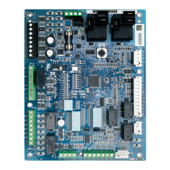
- Page 5 (antifreeze) operation Communications and HWG Settings Factory Low Voltage Molex Connection for Unit Harness Accessory relays refer to DXM2.5 AOM for configuration Electric Heat Connection 24V to Compressor Second-stage Solenoid Use 4 Mounting for Y2/Full Load Capacity Screws –...
-
Page 6: Physical Dimensions And Layout
WATER-SOURCE HEAT PUMPS DXM2.5 Unit Control C r e a t e d : O c t o b e r 1 8 , 2 0 2 2 Physical Dimensions and Layout 5" (240Vac) (240Vac) A+ 24V N.C. N.O. N.O. -
Page 7: Dxm2.5 Controls
By momentarily pressing the TEST pushbutton, the Not Clipped = AL1 connected to R (24VAC) with Alarm DXM2.5 control enters a 20 minute test mode period Relay active. in which all time delays are sped up 15 times. Upon... - Page 8 DIP 3.1 – Communications Configuration: Provides On = Normal Fan Mode. Off = Dehumidification Mode. selection of the DXM2.5 operation in a communicating system. The DXM2.5 may operate as a communicating DIP 1.6 – DDC Output at EH2: DIP Switch 1.6 provides master or slave device depending on the network selection for DDC operation.
-
Page 9: Safety Features
Dedicated Dehumidification Mode option – Dehumidistat from a fault input. The DXM2.5 Control will stage off the Dedicated Dehumidification outputs and then “try again” to satisfy the thermostat Mode option – Humidistat call for compressor. - Page 10 C r e a t e d : O c t o b e r 1 8 , 2 0 2 2 DXM2.5 Controls, Cont’d. Table 3: LED and Alarm Relay Output DXM2.5 CONTROLLER FAULT CODES DXM2.5 Fault and Status LED Operation with Test Mode Not Active Fault LED (Red) Status LED (Green) Alarm Relay DXM2.5 is non-functional...
- Page 11 For this fault least 0.5 seconds, then normal operation is restored. condition, the control will continue to operate using This is not considered a fault or lockout. If the DXM2.5 default operating parameters. is in over/under voltage shutdown for 15 minutes, the Alarm Relay will close.
-
Page 12: Unit Operation Descriptions
The LED’s will indicate the current operating status of the configurations, all Compressor relays and related DXM2.5, as well as the LAST fault in memory. If there is functions will track with their associated DIP1.2. no fault in memory and the fault display is selected, the Fault LED will flash Code 1. - Page 13 The configurations include: turned on immediately. With continuing Emergency Heat a) No Blower: If the DXM2.5 is configured for no blower demand, EH2 will turn on after 5 minutes. EH1 and EH2 (split system compressor sections), the K1 relay...
- Page 14 Cooling input takes priority over dehumidification input. DXM2.5 is programmed to ignore a dehumidification demand when the unit is in heating mode. Above inputs assume DIP 1.3 is in the heat pump position, and DIP 1.4 is in the O position. When 1.3 is in the heat/cool position, Y1 and Y2 are used for cooling inputs; W and O are used for heating inputs.
-
Page 15: Special Dxm2.5 Application Notes
NOTE: If there are no Accessory relays configured c) HWG test mode (S3–2) for Digital NSB, and the DXM2.5 is not connected to a communicating thermostat configured for Internal Flow Center [IFC] Operation: When the night setback, then the NSB and OVR inputs are DXM2.5 is configured to operate the variable speed... - Page 16 When Digital NSB is NOT selected via the Accessory or dehumidistat input to terminal “H” (DIP switch Relays DIP switch inputs and a communicating settings for the DXM2.5 board are shown in table 2), or thermostat configured for night setback is not connected, the manufacturer’s communicating thermostat. Upon when the NSB input is connected to Ground “C”, then...
- Page 17 THE SMART SOLUTION FOR ENERGY EFFICIENCY DXM2.5 Unit Control C r e a t e d : O c t o b e r 1 8 , 2 0 2 2 DXM2.5 Controls, Cont’d. for a 2 hour override period. If NSB is connected to ground If DIP2.7 = on then the H input is defined as Automatic...
-
Page 18: Other Outputs
Electric Heat: Outputs EH1 and EH2 turn on whenever The Condensate Sensor can also essentially be any open the DXM2.5 Control is in the following modes: Heating contact that closes upon a fault condition. Stage 3, Emergency Heat, and Boilerless Operation. - Page 19 THE SMART SOLUTION FOR ENERGY EFFICIENCY DXM2.5 Unit Control C r e a t e d : O c t o b e r 1 8 , 2 0 2 2 DXM2.5 Controls, Cont’d. Table 9: Nominal Resistance at Various Temperatures...
- Page 20 Safety Listing: The DXM2.5 Control is listed under UL The thermistor resistance should be measured with the 873, and is CE listed under IEC 60730.
-
Page 21: General
ON when a motorized water valve with end switch To properly configure and troubleshoot advanced control wired to the DXM2.5 Y1 is used with a communicating features, and to aid in troubleshooting basic control thermostat. For all other system configurations, the features, a communicating thermostat or diagnostic tool Motorized Valve option should be set to OFF. -
Page 22: Service Mode
Control Diagnostics: The Control Diagnostics menus position for only the master DXM2.5, and S3-1 in the allow the installer to see the current status of all DXM2.5 OFF position for all slave DXM2.5 controls. control switch inputs, values of all temperature sensor 3. -
Page 23: Functional Troubleshooting Flow Chart
C r e a t e d : O c t o b e r 1 8 , 2 0 2 2 Functional Troubleshooting Flow Chart Use the following troubleshooting flow chart to find appropriate troubleshooting strategies on the following pages for the DXM2.5 control and most water source heat pump applications. DXM2.5 Functional Start... -
Page 24: Functional Troubleshooting
Check for line voltage between L1 and L2 on the contactor. Main Power Problems Green Status LED Off Check for 24VAC between R and C on DXM2.5. Check primary/secondary voltage on transformer. Check the fuse continuity (remove from circuit and measure resistance). - Page 25 THE SMART SOLUTION FOR ENERGY EFFICIENCY DXM2.5 Unit Control C r e a t e d : O c t o b e r 1 8 , 2 0 2 2 Functional Troubleshooting, Cont’d. Table continued from previous page. Fault...
- Page 26 Unit locked out Check for lockout codes. Reset power. Only Fan Runs Compressor overload Check compressor overload. Replace if necessary. Check thermostat wiring at DXM2.5. Put in Test Mode and jumper Y1 and R Thermostat wiring to give call for compressor.
-
Page 27: Performance Troubleshooting
THE SMART SOLUTION FOR ENERGY EFFICIENCY DXM2.5 Unit Control C r e a t e d : O c t o b e r 1 8 , 2 0 2 2 Performance Troubleshooting Symptom Htg Clg Possible Cause Solution Dirty filter Replace or clean. - Page 28 Check G wiring at heat pump. Jumper G and R for fan operation. Thermostat wiring Check thermostat wiring at or DXM2.5. Put in Test Mode and then jumper Y1 and W1 to R to give call for fan, compressor, and electric heat.
- Page 29 THE SMART SOLUTION FOR ENERGY EFFICIENCY DXM2.5 Unit Control C r e a t e d : O c t o b e r 1 8 , 2 0 2 2 Notes:...
- Page 30 WATER-SOURCE HEAT PUMPS DXM2.5 Unit Control C r e a t e d : O c t o b e r 1 8 , 2 0 2 2 Notes:...
- Page 31 THE SMART SOLUTION FOR ENERGY EFFICIENCY DXM2.5 Unit Control C r e a t e d : O c t o b e r 1 8 , 2 0 2 2 Notes:...
-
Page 32: Revision History
Statements and other information contained herein are not express warranties and do not form the basis of any bargain between the parties, but are merely our opinion or commendation of its products. © Climate Control Group, Inc. All rights reserved 2022...
Need help?
Do you have a question about the DXM2.5 and is the answer not in the manual?
Questions and answers