
Summary of Contents for Aquatek ATWS Series
- Page 1 ATCWS | Atws | ATWS-C/CC | ATWS-HI | ATnWS | ATTWS Operation & Maintenance Manual United Water Inc | 1-877-414-PURE(7873) | www.unitedwaterinc.com | unitedwatercorp@gmail.com...
-
Page 2: Table Of Contents
Table of Contents Introduction Meet Your Water Softener Installation Guide Installation Diagram System Start-Up Programming Guide Manual Regeneration The Brine System Parts Breakdown Trouble Shooting Guide UNITED WATER INC. AtWS-S quAtek erieS uide... - Page 3 ***ATTENTION*** ATWS System Specifications & Warnings System Specifications Water pressure: 40 psi minimum 100 psi Maximum Water Temperature: 40°F to 110°F Electrical Requirements: Supply Voltage: 120V Supply Frequency: 60Hz Output Voltage: 12V AC Output Current: Maximum 3.0 Amps Water Meter: Pipe Size: 3/4”-1”...
-
Page 4: Introduction
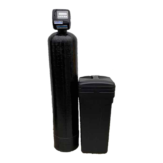
Introduction Please Read Manual First Before you operate your Aquatek Water Softener, read this manual to become familiar with the device and its capabilities. Installation or maintenance done on this system by an untrained service person can cause major damage to equipment or property damage. - Page 5 Two Tank Systems All Aquatek Two Tank Water Softeners are comprised of three primary components: (A) Control Valve, (B) Mineral Tank, & (C) Brine Tank. A Control Valve A. Control Valve: Your control valve automatically performs 3 primary operations which are commonly referred to as cycles.
- Page 6 PRINCIPLES OF ION EXCHANGE IN THE SOFTENING PROCESS 1. ION EXCHANGE SOFTENING PROCESS In order to understand what happens in the ion exchange softening process, it will first be necessary to understand the meaning of the terms that are used in the explanation. HARD WATER, CATION EX- CHANGER, and BRINE are therefore defined below and then used to show how the ion exchange pro- cess works.
- Page 7 2.3 CAPACITY OF ION EXCHANGER The capacity for the removal of calcium and magnesium depends mainly upon the type of ion ex- changer that is used. It is further influenced by the amounts of hardness and sodium ions in the raw water, and by the amount of salt used for regeneration.
-
Page 8: Installation Guide
Installation Guide Pre-Installation Checklist 1. A standard electrical outlet (120V/160Hz) must be located within 12’ of installation site. 2. A functioning floor drain, washer sand pipe or suitable location for waste water discharge must be located within 20’ of installation site. a. - Page 9 Installation CONT. 7. Locate Polytube Insert: Now that the water softener is connected to the existing plumbing, the drain line may be connected. First, locate and remove the polytube insert (#2) from the gray cable on the left side of the control valve. 8.
-
Page 10: Installation Diagram
Installation Diagram Below are two typical installation examples: 1. Well Water & 2. City Water. Please reference the flow diagram and placement of system(s) to ensure your system will be functioning properly. ***Disclaimer*** United Water strongly recommends that each system be installed by a licensed and knowledgeable professional. -
Page 11: System Start-Up
AND place all other systems not be- ing started in bypass to avoid flushing debris/contaminates across systems To start-up your Aquatek ATWS Softener begin by placing the by- Fig. 1 pass in the position shown in Figure 1 and adding salt to your brine... -
Page 12: Programming Guide
Programming Guide Aquatek Water Softener Control Valve Programming & Operation During normal operation one of three screens can be displayed. Pressing the NEXT button alternates be- tween these screens. Screen 1 - Current Time of Day Screen 2 - Capacity Remaining in Gallons UNITED WATER INC. - Page 13 Your control valve has been pre-programmed from the factory with the correct regeneration cycle pro- gram and cycle times. The gallon capacity between regeneration can be changed by adjusting the water hardness. Step 1 - Press the NEXT and the UP Arrow buttons at the same time and hold for 2 seconds. Step 2 - Raw Water Hardness: Adjust to the correct hardness by pressing the UP or DOWN arrow button.
-
Page 14: Manual Regeneration
Manual Regeneration There are two different purposes and methods for manual regeneration of the water softener. • Delayed Regeneration • Immediate Regeneration Reasons you may want to manually regenerate the water softener: 1. If the brine tank has run out of salt: •... -
Page 15: The Brine System
The Brine System Your Aquatek water softener utilizes a salt brine system in order to regenerate and refresh the soften- ing capibilites of your system. Two Tank systems (ATWS) have an extrnal Brine Tank and Cabinet Systems (ATCWS) have a brine chamber inside the cabinet. Regardelss of model you will need to perform peroidic matainence, system cleaning, and replenshing of salt levels. - Page 16 Square Brine Tank Brine Tank interanal compoents & functionality of parts are essen- tially the same regardless of whether you have a square or a round tank. The only real differences are the shape of the Salt Shelf/Tank Grid, and the Brine Valve Assembly. If you any questions we’re here to help - call us at 1-877-414-PURE (7873) 1.
-
Page 17: Parts Breakdown
Parts Breakdown Front Cover and Drive Assembly Drawing Part Number Number Description Qty. V3175-01 Front Cover Assembly V3107-01 Drive Motor V3106-01 Drive Bracket and Spring Clip V3108 Circuit Board V3110 Drive Reducing Gear V3109 Drive Gear Cover V3186 Transformer 110VAC-12VAC Shown Main Body Internals Drawing... - Page 18 Front Cover and Drive Assembly Injector – A Black Injector – B Brown Drawing Part Injector – C Violet Number Number Description Qty. Injector – D Red Injector – E White V3176 Injector Cap Injector – F Blue Injector – G Yellow V3152 O-Ring Injector Cap Injector –...
- Page 19 1” Drain Assembly (Optional) Drawing Part Number Number Description Qty. H4615 Elbow Locking Clip V3008-02 Drain Footing Straight V3166 Drain Footing Body V3167 Drain Fooring Adapter V3163 O-Ring V3150 Split Ring V3151 1” Nut V3105 O-Ring V3190-XX DLFC (specify size) Bypass Assembly Drawing Part...
- Page 20 Standard 1” Male NPT Elbow Installation Fittings Drawing Part Number Number Description Qty. Standard 1” Male NPT Elbow V3151 1” Nut V3150 Split Ring V3105 O-Ring V3149 1” Fitting PVC Male NPT Elbow Optional PVC Elbow V3151 1” Nut V3150 Split Ring Optional PVC Elbow V3105...
-
Page 21: Trouble Shooting Guide
Trouble Shooting Guide Problem Possible Cause Solution No power at electrical outlet Repair outlet or use working outlet Control Valve Power Cord not plugged Make sure Control Valve Power Cord is onto Control Valve Circuit Board connected securely at both ends No display on Control Valve Circuit Board Improper power supply... - Page 22 Problem Possible Cause Solution Bypass Valve is open or faulty Fully close Bypass Valve or replace. Also check for multiple bypasses Media is exhausted due to high water Check program settings or diagnostics for abnormal water usage usage Meter not registering Remove Meter and check for rotation or foreign material Water quality fluctuation...
- Page 23 Problem Possible Cause Solution Injector is plugged Remove Injector and clean or replace Faulty Brine Piston Replace Brine Piston Brine line tubing connection leak Inspect Tubing and Fittings for air leak Drain line restriction or debris can Inspect drain line and clean to correct Control Valve fails to cause excess back pressure on Injector restriction...
- Page 24 Problem Possible Cause Solution Motor failure during a regeneration Check motor connections then Press NEXT and REGEN buttons at the same time for 3 seconds to resynchronize software with piston. Err - 1003 = Control Foreign matter built up on Piston and Replace Piston and Seal and Spac- valve motor ran too Seal and Spacer Stack Assemblies cre-...
- Page 25 Manufacturer’s Limited Warranty The manufacturer warrants to the original owner that its Water Conditioning Equipment will be free from defects in material and workmanship under normal use and service for a period of five (5) years from the date of installation, when installed and operated with- in recommended parameters.
Need help?
Do you have a question about the ATWS Series and is the answer not in the manual?
Questions and answers