Table of Contents
Advertisement
Quick Links
Advertisement
Table of Contents

Summary of Contents for LOGICO 2 MkVII
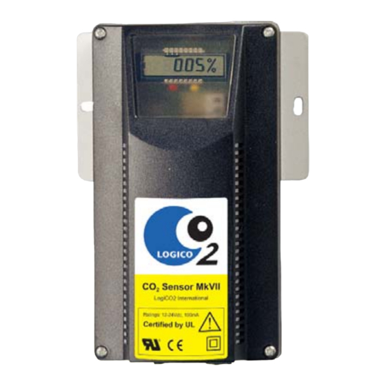
- Page 1 User’s Manual MkVII CO 2 Safety System...
-
Page 2: Table Of Contents
Please note that whenever installing or disconnecting a system, refer to this manual first! Table of contents Safety..........................3 Purpose of CO2 detection General Description ...................... 4-6 Product description and Performance Temperature surveillance Function of Central Unit Function of Sensor Installation ........................7-8 Connection Diagrams .................... -
Page 3: Safety
Safety I IMPORTANT All persons responsible for the use and maintenance of this equipment must read and understand the safety and operating information contained in this guide. Installation and service of this equipment should be performed only by professionals. The function of the equipment will be impaired if it is not properly installed. -
Page 4: General Description
II General Description and Alarm/Alert (red LED). A buzzer sounds Product Description and Performance when there is a error or alarm/alert. Error and alerts are indicated by a intermittent sound and The Carbon Dioxide (CO2) Safety System is alarm by a continuous sounding buzzer. designed to measure CO2 concentration in a •... - Page 5 General Description II At the low alarm level the tone may be switched off by pressing the reset button shortly. At a low alarm, the red LED will continue until the CO2 level drops below 1.5% (the low alarm). At a Low Alarm, one person, supervised by another, may check for the leakage cause.
- Page 6 II General Description The warning signs provided with the CO 2 Safety System. All signs must be mounted in a secure, permanent way to eliminate any risk that they fall down. Sign 1 ”CO2 Safety System” should be placed next to the central unit. CO2 Safety System What to do in case of an ALARM? 1.
-
Page 7: Installation Iii
Installation III - The sensor should be installed so it has Observe the System’s Operation clear exposure to room air but is away from ventilation inlets or outlets. Its digital display The CO2 Safety System is packaged with its sensor, should be visible. - Page 8 III Installation Install the Horn/Strobe The CO2 Safety System is equipped with a pre- wired horn/strobe. Its power cord has a blue connector at the end terminal that is connected it to the splitter, marked with a blue dot. 1. Mount the horn/strobe in a proper location above the CO2 sensor.
-
Page 9: Connection Diagrams
IV Connection Diagrams Connection diagram For US market Important! The sensor shall be CO2 Safety System mounted 12 inches or 30 WARNING WARNING What to do in case of an ALARM? 1. Keep Calm ! 2. Turn off the acoustic alarm on the blue Central Unit by pressing the RESET button on the bottom right side. - Page 10 IV Connection Diagrams CO2 Sensor unit Jumpers Connected (default) Disconnected AZC deactivated AZC activated JP52 Relay 1 Common to voltage Relay 1 potential free JP53 Relay 2 Common to voltage Relay 2 potential free JP56 Temp deactivated Temp activated JP59 LogiCO2-program MODBUS Central unit...
-
Page 11: Important Records V
Important Records V Proper function of this product is entirely dependent on its correct installation. The five-year warranty as of the date of installation is only valid when this form has been completed. Installing Company: Name of installer: _________________________________________ _____________________________________ The Logi CO2 Safety System has been properly installed and tested by an authorized person. - Page 12 V Important Records Example of proper placement of Sensor (black), Control Unit (blue) and Horn/Strobes (white). Illustration shows a backroom/basement installation Function test Sensor Date Name No 1 Date Name No 2 Date Name No 3 Date Name No 4 Date Name No 5...
-
Page 13: Ordering Service And Parts Vi
6. Cleaning is done by use of water on a moistened cloth. Ordering Parts or Service CO2 Set 1, Fahrenheit Part.no. CO2 SET 1 UL MKVII B CO2 Set 1, Celsius Part.no. CO2 SET 1 CE MKVII B CO2 Central Unit Part.no. -
Page 14: Specifications
VII Specifications CO 2 SENSOR Product: Operating principle Non-dispersive infrared (NDIR) and thermistor Measurement range - temperature 0...+40°C (+32°F...+102°F) Measurement range - CO 2 0-3 Vol.% Extended range - CO 2 3-10 Vol.% Gas sampling mode Diffusion TWA: Time Weighted Average (TWA) calculation 8 h time span (most recent) with 4 min sample period. (Pat. Pend.) Accuracy: Temperature: ±1°C (±1.8°F) - Page 15 Specifications VII CO 2 CENTRAL UNIT 12-24V DC Supply: 40 mA Current consumption: RS485, Modbus Communication: Two row: 2 x 8 digit Display: 70 dB (1m) max. Acustic signal-strength: 0-40°C (+32°F...102°F) Ambient temperatures: 0-90% non-condensing Humidity: IP 20 Ingress protection: CE: Emission tests according SS-EN 61000-6-3 and the immunity Approval: tests according to SS-EN 61000-6-2.
-
Page 16: Warranty Viii
Warranty VIII LogiCO2’s sole and exclusive liability under this Warranty Policy Warranty is to the Purchaser and shall not exceed the LogiCO2 warrants to the Purchaser of the CO2 Safety lesser of the cost of repair, cost of replacement, or System equipment for 2 years from the installation refund of the net purchase price paid by the original date.
Need help?
Do you have a question about the MkVII and is the answer not in the manual?
Questions and answers