Table of Contents
Advertisement
FOR YOUR SAFETY
If you smell gas:
1. Open windows.
2. DO NOT try to light any appliance.
3. DO NOT use electrical switches.
4. DO NOT use any telephone in
your building.
5. Extinguish any open flame.
6. Leave the building.
7. Immediately call your local gas
supplier after leaving the building.
Follow the gas supplier's
instructions.
8. If you cannot reach your gas
supplier, call the Fire Department.
WARNING
Fire Hazard
Keep all flammable objects, liquids and
vapours the minimum required
clearances to combustibles away from
heater.
Some objects will catch fire or explode
when placed close to heater.
Failure to follow these instructions can
result in death, injury or property
damage.
WARNING
Improper installation, adjustment, alteration, service
or maintenance can result in death, injury or
property damage. Read the Installation, Operation
and Service Manual thoroughly before installing or
servicing this equipment.
Installation must be done by an electrician qualified
in the installation and service of control systems
for heating equipment.
© 2015 Combat HVAC Limited
N
Energy Saving Control for
Combat HVAC infrared and
warm Air Heating Equipment
Installation, Operation and Service Manual
Please take the time to read and understand
Installer must give a copy of this manual to the owner.
Keep this manual in a safe place in order to provide
your service technician with necessary information.
Combat HVAC Ltd
Unit A, Kings Hill Business Park
Darlaston Road, Wednesbury
West Midlands, WS10 7SH UK
Telephone: +44 (0)121 506 7700
Fax: +44 (0)121 506 7701
Service Telephone: +44 (0)121 506 7709
Service Fax: +44 (0)121 506 7702
E-mail: uksales@combat.co.uk
E-mail: export@combat.co.uk
www.combat.co.uk
www.blackheatheaters.co.uk
RG Control
Installer
these instructions prior to any installation.
Owner
P/N X235 Rev H1 04/15
Advertisement
Table of Contents

Summary of Contents for Combat HVAC NRG Control
- Page 1 West Midlands, WS10 7SH UK Telephone: +44 (0)121 506 7700 Fax: +44 (0)121 506 7701 Service Telephone: +44 (0)121 506 7709 Service Fax: +44 (0)121 506 7702 E-mail: uksales@combat.co.uk E-mail: export@combat.co.uk www.combat.co.uk © 2015 Combat HVAC Limited P/N X235 Rev H1 04/15 www.blackheatheaters.co.uk...
-
Page 3: Table Of Contents
TABLE OF CONTENTS SECTION 1: Introduction............2 1.1 Safety Labels and Their Placement ......2 1.2 What is an NRG Control? ..........2 1.3 General Requirements ..........2 1.4 Control Location ............2 1.5 Network Installation............2 1.6 Installation Requirements..........3 1.7 Programming Details ............ - Page 5 TABLE OF FIGURES Figure 1: Keypad Layout ............4 Figure 2: Remote Sensors ............5 Figure 3: Cover Detail ............... 6 Figure 4: Mounting Hole Layout ..........6 Figure 5: Cable Entry ..............7 Figure 6: Control Terminals and Relay Use....... 7 Figure 7: Ferrite EMC Filter ............
- Page 7 Product Approval Combat HVAC appliances have been tested and CE certified as complying with the essential requirements of the Gas Appliance Directive, the Low Voltage Directive, the Electromagnetic Compatibility Directive and the Machinery Directive for use on natural gas, LPG and fuel oil when installed, commissioned and maintained in accordance with these instructions.
-
Page 8: Section 1: Introduction
Combat HVAC System Control will be required with a Installation, service and annual inspection of Combat HVAC NRG Control installed for each zone. -
Page 9: Installation Requirements
DANGER 1.6 Installation Requirements 1.6.1 Radiant Tube Heaters The Combat HVAC NRG Control can operate up to ten burners providing that the electrical load on each relay does not exceed 7 A inductive. Mount Combat HVAC NRG Control (or remote sensor if fitted) on a wall or column at a height of approximately 1.5 to 1.8 metres from the floor. -
Page 10: Section 2: Specifications
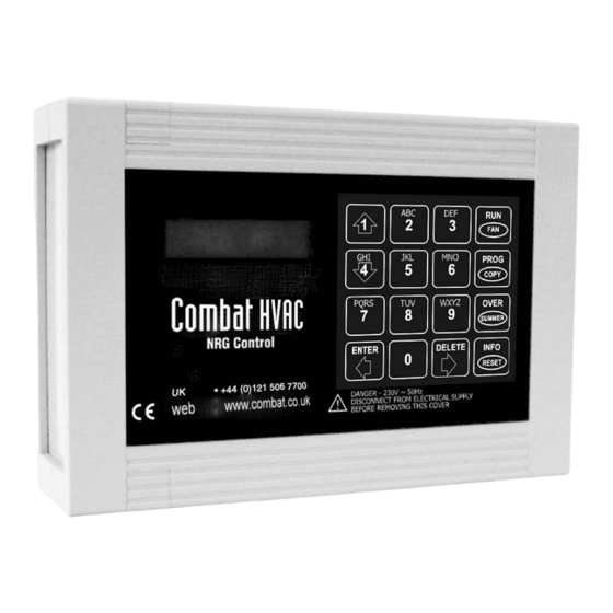
SECTION 2: SPECIFICATIONS Figure 1: Keypad Layout PROG COPY Combat HVAC OVER SUMMER ENTER DELETE NRG Control INFO RESET DANGER - 230 V 50 Hz • +44 (0)121 506 7700 DISCONNECT FROM ELECTRICALSUPPLY • www.combat.co.uk BEFORE REMOVING THIS COVER 2.1 Material... -
Page 11: Figure 2: Remote Sensors
SECTION 2: S PECIFICATIONS 9. Enter key to confirm inputs (move backward around network). 10.Temperature adjustment (optional, between engineer defined limits) reverts to programmed set point at next switch on. Figure 2: Remote Sensors Temperature Sensor Black Bulb Sensor Sports Hall Sensor (Wire On Site) Description Part Number... -
Page 12: Section 3: Installation
Controller must be properly grounded to an electrical source. Failure to follow these instructions can result in death or electrical shock. Installation of Combat HVAC NRG Control must be done by an electrician qualified in the installation of Description Part Number control systems for heating equipment. -
Page 13: Electrical Installation Requirements
SENSORS concerned. Unitary CRV - Multi Failure to comply will cause permanent damage Warm Air Burner Radiant Radiant to burner control on heater and Combat HVAC Relay 1 NRG Control. Burner or 3.3.5 Network Connections Burner Burner Relay 2 Low Fire Optionally controls may linked together as described on Page 2, Section 1.5. -
Page 14: Figure 8: Sensor Mounting Plate - Warm Air
HVAC RG C OMBAT ONTROL NSTALLATION PERATION AND ERVICE ANUAL Figure 8: Sensor Mounting Plate - Warm Air Figure 10: Sports Hall Sensor Remote sensors must be fastened using countersunk screws. Dome headed screws will short out the board and result in failure of the sensor. -
Page 15: Section 4: Wiring
SECTION 4: W IRING SECTION 4: WIRING DANGER Electrical Shock Hazard Disconnect electric before service. More than one disconnect switch may be required to disconnect electric to the unit. Failure to follow these instructions can result in death or electrical shock. 4.1 Network Wiring 9 of 40... -
Page 16: Low Voltage Wiring
HVAC RG C OMBAT ONTROL NSTALLATION PERATION AND ERVICE ANUAL 4.2 Low Voltage Wiring 10 of 40... -
Page 17: Ctu Wiring (Pektron Ignition Controller)
SECTION 4: W IRING 4.3 CTU (Terminal block connection) Wiring (Pektron Ignition Controller) 4.4 CTCU Wiring & CTU (7 pin plug connection) (Pektron Ignition Controller) 11 of 40... -
Page 18: Ctu Wiring (Pactrol Ignition Controller)
HVAC RG C OMBAT ONTROL NSTALLATION PERATION AND ERVICE ANUAL 4.5 CTU Wiring (Terminal block connection) (Pactrol Ignition Controller) 4.6 CTCU Wiring & CTU (7 pin plug connection) (Pactrol Ignition Controller) 12 of 40... -
Page 19: Interface Relay Wiring For Multiple Models Ctu 70 - 115
SECTION 4: W IRING 4.7 Interface Relay Wiring for Multiple Models CTU 75 - 115 Description Part Number Interface Relay Assembly D258 13 of 40... -
Page 20: Interface Relay Wiring For Multiple Models Ctcu 11 - 32 & Ctu 40 - 60
HVAC RG C OMBAT ONTROL NSTALLATION PERATION AND ERVICE ANUAL 4.8 Interface Relay Wiring for Multiple Models CTCU 11 - 32 & CTU 40 - 60 Description Part Number Interface Relay Assembly D258 14 of 40... -
Page 21: Mgb/Mob Range Wiring - 1 Ø Cabinet Heaters
SECTION 4: W IRING 4.9 MGB/MOB Range Wiring - 1 Ø Cabinet Heaters 15 of 40... -
Page 22: Mgb/Mob Range Wiring - 3 Ø Cabinet Heaters
HVAC RG C OMBAT ONTROL NSTALLATION PERATION AND ERVICE ANUAL 4.10 MGB/MOB Range Wiring - 3 Ø Cabinet Heaters 4.11 Cabinet Heater Remote Lockout Reset Wiring (With THERMOWATT Ignition Control) 16 of 40... -
Page 23: Cabinet Heater Remote Lockout Reset Wiring
SECTION 4: W IRING 4.12 Cabinet Heater Remote Lockout Reset Wiring (older versions) 4.13 Unitary Radiant System Wiring 17 of 40... -
Page 24: Corayvac And Multiburner Systems Wiring
HVAC RG C OMBAT ONTROL NSTALLATION PERATION AND ERVICE ANUAL ® 4.14 CORAYVAC and Multiburner Systems Wiring CAUTION Product Damage Hazard Do not directly connect control relay terminals to pump motor. Failure to follow these instructions can result in product damage. 18 of 40... -
Page 25: Section 5: Programming And Operation
2. Calibrate temperature sensor; Page 36, Sec- 5.3 System Language tion 5.6.5. The Combat HVAC NRG Control has been 3. Set optimisation; Page 32, Section 5.6.2. programmed to display in 5 languages. The remainder of the settings may be undertaken in To select or change the language See Page 19, any order. - Page 26 HVAC RG C OMBAT ONTROL NSTALLATION PERATION AND ERVICE ANUAL 5.3.2 Default Settings The following settings are factory defaults and will be active following a system reset. Function Section Default Setting Network Setting Stand Alone Network Defaults Network Access Code 5.6.1 Empty Network Configuration Code...
-
Page 27: Network Open Level User Functions
SECTION 5: P ROGRAMMING AND PERATION 5.4 Network Open Level User Functions 21 of 40... - Page 28 HVAC RG C OMBAT ONTROL NSTALLATION PERATION AND ERVICE ANUAL 5.4.1 Information 5.4.2 Lockout Reset WARNING Explosion Hazard If control locks out, do not make more than three attempts to restart the heater. Dangerous gas mixtures can build up. The fault must be traced and repaired by a registered installer or service engineer.
- Page 29 SECTION 5: P ROGRAMMING AND PERATION 5.4.3 Override and Summer Mode ZONE NAME 20°C ZONE NAME 20°C HEAT OFF SUMMER PRESS OVER If user code programmed SUMMER in engineer set up, then enter user code. TO DELETE WRONG ENTRY ** WARNING! ** If user code not programmed in engineer set up, then ENTRY CODE: ????
- Page 30 HVAC RG C OMBAT ONTROL NSTALLATION PERATION AND ERVICE ANUAL 5.4.4 Manual Fan Operation 24 of 40...
-
Page 31: Manager Settings
SECTION 5: P ROGRAMMING AND PERATION 5.5 Manager Settings 5.5.1 Manager Network Access 25 of 40... - Page 32 HVAC RG C OMBAT ONTROL NSTALLATION PERATION AND ERVICE ANUAL 5.5.2 Set Temperature ZONE NAME 20°C HEAT OFF PROG COPY Enter manager code four digits. ** WARNING! ** Factory default code 0000. See engineer set up for ENTRY CODE: ???? alternative access to manager codes.
- Page 33 SECTION 5: P ROGRAMMING AND PERATION 5.5.3 Set Operating Times Network Control Stand Alone ZONE NAME 20°C Control HEAT OFF PROG COPY Enter manager ** WARNING! ** code four digits. Factory default Enter from ENTRY CODE: ???? code 0000. Exit to Network Network Control See engineer set up for alternative...
- Page 34 HVAC RG C OMBAT ONTROL NSTALLATION PERATION AND ERVICE ANUAL 5.5.4 Set System Time and System Code 28 of 40...
- Page 35 SECTION 5: P ROGRAMMING AND PERATION 5.5.5 View Logged Data 29 of 40...
- Page 36 HVAC RG C OMBAT ONTROL NSTALLATION PERATION AND ERVICE ANUAL 5.5.6 Set Holiday Period Network Control Stand Alone Control ZONE NAME 20°C HEAT OFF PROG COPY Enter manager code ** WARNING! ** four digits. Factory default code 0000. ENTRY CODE: ???? See engineer set up for alternatives access to ENTER...
-
Page 37: Engineer Settings
SECTION 5: P ROGRAMMING AND PERATION 5.6 Engineer Settings All engineer settings must be carried out at individual control. 5.6.1 Network Configuration 31 of 40... - Page 38 HVAC RG C OMBAT ONTROL NSTALLATION PERATION AND ERVICE ANUAL 5.6.2 Set Override Hours and Optimisation 32 of 40...
- Page 39 SECTION 5: P ROGRAMMING AND PERATION 5.6.3 Set Access Code and Configure 33 of 40...
- Page 40 HVAC RG C OMBAT ONTROL NSTALLATION PERATION AND ERVICE ANUAL Table 1: Recommended Configuration Settings for Appliance Type Function Type ON/OFF Pressure Screen path from HI/LO High Flame Boost Fan Purge Double Ignition Switch Fan Options engineer code 4 - 1 4 - 1 - (1) 4-1-(0 or 2)-1 4 - 1 - (0, 1 or 2)
- Page 41 SECTION 5: P ROGRAMMING AND PERATION 5.6.4 Set Fan Operation 35 of 40...
- Page 42 HVAC RG C OMBAT ONTROL NSTALLATION PERATION AND ERVICE ANUAL 5.6.5 Set Sensor Calibration 36 of 40...
- Page 43 SECTION 5: P ROGRAMMING AND PERATION 5.6.6 Set Service Mode 37 of 40...
- Page 44 HVAC RG C OMBAT ONTROL NSTALLATION PERATION AND ERVICE ANUAL 5.6.7 System Reset 38 of 40...
-
Page 45: Section 6: Standard Screen Messages
SECTION 6: S TANDARD CREEN ESSAGES SECTION 6: STANDARD SCREEN MESSAGES 6.1 Stand Alone Control Screen Messages 39 of 40... -
Page 46: Network Control Screen Message
HVAC RG C OMBAT ONTROL NSTALLATION PERATION AND ERVICE ANUAL 6.2 Network Control Screen Message ZONE NAME 20°C = This control currently being accessed by another network control. UNDER NW CONTROL = This control cannot connect to the network. Check network wiring and NETWORK ERROR 01 configuration.
Need help?
Do you have a question about the NRG Control and is the answer not in the manual?
Questions and answers