
Summary of Contents for Koch AVC1
-
Page 1: Table Of Contents
Product Information Video Cloud Gateway AVC1 Index Page Product description - Intended use - Scope of functions Safety instructions Technical data Device overview - Display of control elements Assembly and installation - Assembly on DIN rail - Connection Operation - HW Settings... -
Page 2: Product Description
Product description Intended use The AVC1 device is a cloud gateway with an integrated video server. It converts TC:Bus signals to network protocol (IP) level and connects the KochCloud to the TC:Bus. The device is designed to be mounted on a DIN rail in the control cabinet. To carry out any programming, the user must have an external device (e.g. -
Page 3: Safety Instructions
Safety instructions The safety regulations for high-voltage installations must be observed when working on systems with a 230 V AC mains connection. Only qualified electricians may carry out the assembly, installation and start-up work. The general safety regulations for telecommunications systems apply to the installation of TC:Bus systems. -
Page 4: Device Overview
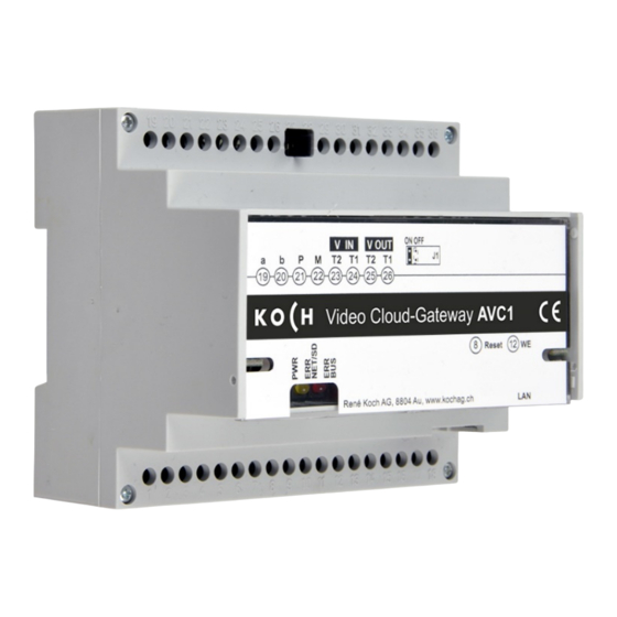
Device overview Terminals a, b, P, M, Video-IN and -OUT Terminals Terminating resistor (jumper) LED, green (ready for use indicator light) LED, yellow (network and SD Display and control elements card error indicator light) LED, red (TC:Bus error indicator light) Reset button (device restart) WE button (restore factory settings) -
Page 5: Assembly And Installation
Assembly and installation Caution! The AVC1 may only be assembled and dismantled when the device is disconnected from the power supply! T1 and T2 must not be connected with another wire. The polarity should be noted when connecting video wires T1 (-) and T2 (+). -
Page 6: Connection
Network connection: RJ45 patch cable (CAT.5 FTP 8-pin) • Connect the TC:Bus wires (a, b, P, M, T2, T1) as per the installation diagram provided • Connect the RJ45 interface of the AVC1 and network with a patch cable 6/12... -
Page 7: Operation
If the image is unclear after the device has been started up, switch it off and swap the wires for the video signal HW Setting (De)activate the terminating resistor If the AVC1 device is installed at the end of a TC:Bus video line, the jumper for the terminating resistor must be set ON OFF to the ON position (factory setting) •... -
Page 8: Network Settings
Network settings Installing an IP network is a very intricate procedure due to the numerous interdependent parameters and settings. The procedure requires a lot of background knowledge. Please contact your network administrator for this. IP addresses and DHCP server Every device used in a network requires an IP address. Devices that communicate with each other must also be on the same subnet. - Page 9 • Management of Admin and User passwords (De)activate DHCP • Start STC-C on PC • Check or uncheck the DHCP checkbox • Update the EEPROM from the AVC1. For more information about STC-C refer to the program’s help section. Password = AVC1 serial number 9/12...
- Page 10 Notes 10/12...
- Page 11 11/12...
-
Page 12: Service
You can find answers in our list of frequently asked questions www.kochag.ch FAQ (German and French only) >>> For direct support, please contact our technical customer service team: Phone 044 782 6000 René Koch AG Seestrasse 241 8804 Au/Wädenswil 044 782 6000 info@kochag.ch www.kochag.ch sehen hören sprechen...
Need help?
Do you have a question about the AVC1 and is the answer not in the manual?
Questions and answers