Table of Contents
Advertisement
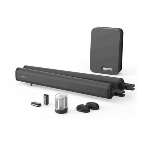
TEHA 410
MOTOR DRIVE KIT
With actuators – For two-panel swing gates
Ref. 114173
EN
24V
PORTAIL
SWING
24V
À BATTANT
GATE
V1
KG
L
1.75M
1,75M
150KG
150KG
PAR BATTANT
PER PANEL
PAR BATTANT
PER PANEL
COMPATIBLE WITH
COMPATIBLE TOUS
OPTION
SOLAR
TYPES DE PORTAILS
WITH ALL TYPES
SOLAIRE
OPTION
OF OPENWORK
GATES
BACKUP BATTERY
OPTION
BACKUP BATTERY
OPTION COMPATIBLE
BATTERIE DE SECOURS
OPTION
SMARTPHONE
SMARTPHONE
COMPATIBLE
www.avidsen.com
3
Advertisement
Table of Contents

Summary of Contents for Avidsen TEHA 410
-
Page 1: Menu
TEHA 410 MOTOR DRIVE KIT With actuators – For two-panel swing gates Ref. 114173 PORTAIL SWING 1,75M 1.75M 150KG 150KG COMPATIBLE WITH COMPATIBLE TOUS OPTION SOLAR BACKUP BATTERY OPTION OPTION COMPATIBLE BACKUP BATTERY À BATTANT GATE PAR BATTANT PER PANEL... -
Page 2: Table Of Contents
CONTENTS A - SAFETY INSTRUCTIONS D - BEGINNING OPERATION 1 - OPERATING PRECAUTIONS 1 - SETTINGS INTERFACE 2 - INSTALLATION PRECAUTIONS 2 - QUICK SETTINGS 2.1 - Self-learning 3 - MAINTENANCE AND CLEANING 2.2 - Adding remote controls 4 - RECYCLING 2.2.1 - Programming with the card 2.2.2 - Copy programming B - PRODUCT DESCRIPTION... - Page 3 E - USE G - TECHNICAL AND LEGAL INFORMATION 1 - WARNINGS 2 - OPENING/CLOSING 1 - TECHNICAL CHARACTERISTICS 2.1 - Type of command 2 - WARRANTY 2.2 - Operating modes 3 - HELP AND ADVICE 2.2.1 - “Semi-automatic closing” mode 32 2.2.2 - “Automatic closing”...
-
Page 4: A - Safety Instructions
A - SAFETY INSTRUCTIONS In our efforts to continually improve our products, Avidsen cannot be held liable for any use that does we reserve the right to make any changes to the not comply with the instructions in this manual and technical, functional, or aesthetic characteristics causes damage. -
Page 5: Maintenance And Cleaning
A - SAFETY INSTRUCTIONS 3 - MAINTENANCE AND CLEANING 4 - RECYCLING • Read all the instructions given in this manual Disposing of used batteries in household before carrying out maintenance on the waste is strictly forbidden. Batteries/ motorised gate. accumulators containing harmful... -
Page 6: B - Product Description
B - PRODUCT DESCRIPTION 1 - CONTENTS OF THE KIT Actuator Remote control Switchgear Photocells Flashing light Gate mounting bracket Post mounting bracket 2 - EQUIPMENT REQUIRED (NOT INCLUDED) The tools and screws required for the installation must be in good condition and compliant with applicable safety standards. -
Page 7: C - Installation
C - INSTALLATION HAZARD ANALYSIS These maximum dimensions and weights are for an openwork-type gate and for use in an area that is not very windy. For use in an area with REGULATION significant wind speed, it is necessary to reduce the maximum values indicated above for the gate Installation of a motorised gate or a motor to be motorised. -
Page 8: Eliminating Risks
C - INSTALLATION SAFETY RULES The actual opening of a gate may create dangerous situations for people, goods and vehicles in the vicinity that by nature, cannot always be avoided by design. The possible hazards depend on the state of the gate, the manner in which it is used and the installation site. -
Page 9: Installing Actuators
C - INSTALLATION Between the panels and the fixed parts close to each other Depending on the configuration of the site where the motorised gate is installed, there may be confinement areas between the panels in open position and the fixed parts close to them. To remove these areas, it is mandatory to leave a safe distance of 500mm between the fixed part and the moving parts of the motorised gate. hazard solution post post confinement area 500mm minimum view from above PREVENTING OTHER HAZARDS The body of a switch with no lock must be located in direct view of the driven part but away from moving parts. -
Page 10: Maximum Opening Angle
C - INSTALLATION 2.1 - MAXIMUM OPENING ANGLE The installation of the actuators depends on the desired opening angle which depends on distance D (the distance between the axis of the hinge and the inner side of the post). Normal case •... - Page 11 C - INSTALLATION Overview Switchgear Flashing light control unit photocells actuators Mandatory central stop (not included) Mandatory side stops (not included) Inner side of the property Attaching the post mounting bracket Mount the actuators to a rigid and reinforced part of the gate (e.g. the frame or the crossbar). Mount them as low as possible for aesthetic and technical reasons.
- Page 12 C - INSTALLATION • The height of the centre of the mounting bracket must be the same as the centre of the gate frame on which the actuator is mounted. post 31mm D (mm) B (mm) max angle (°) 120° 120°...
- Page 13 C - INSTALLATION Battery Rod movement direction 48mm connection Black carriage stop Black free space Assemble the actuator rotation axis with the post mounting bracket Using a butterfly screw, assemble the gate mounting bracket with the actuator. STEP 1: Use the 9 V battery to move the “carriage” to the end of the actuator, then back 0.5 to 1 cm inwards STEP 2: Close the gate by pressing it securely against its central stop, then rotate the...
-
Page 14: Installing The Switchgear
C - INSTALLATION STEP 4: Keep only the mount and fix it to the gate using the appropriate fasteners STEP 5: Use the butterfly screw to reattach the actuator on the mount 3 - INSTALLING THE SWITCHGEAR The switchgear must be mounted to the post where the 230Vac power comes from. •... -
Page 15: Installing The Flashing Light
C - INSTALLATION 4 - INSTALLING THE FLASHING LIGHT The flashing light must be fastened at the top of the post on which the switchgear is attached and must be visible both inside and outside. Only use the light provided in the kit (24 V - 2 W). The flashing light may be fastened on the wall with or without support. • With a screwdriver, remove the transparent part of the flashing light by unscrewing the 2 screws that hold the upper part of the flashing light. • Continuing to use a screwdriver, remove the flashing light bracket by unscrewing the 2 screws inside the light. • Fasten the flashing light bracket to the wall (ignore this step if you are fastening the light directly to the wall). • Run the wires into the flashing light and connect them to the LED lightbulb (maintaining the “+” and “-” polarity). - Page 16 C - INSTALLATION 5 - ATTACHING THE SET OF PHOTOCELLS 1 set of photocells • Install the reception photocell (RX indicated at the back) of the same side of the gate as the switchgear. The surface of the posts must be perfectly flat in order to properly align the infrared beam of the photocells.
- Page 17 C - INSTALLATION 20mm Outer side of the property 2 set of photocells For use when the gate is not visible. You must install a second set of photocells to prevent the gate from opening when an item (car, person, etc.) is behind the gate. •...
-
Page 18: Connections
C - INSTALLATION 6 - CONNECTIONS • The cable run between must comply with applicable standards (NFC 15-100). • Either the cable is 80 cm deep with red warning mesh, or the cable is run through a sheath. 230V vers Safety instructions - All electrical connections must be performed with the power switched off (safety switch in OFF position). -
Page 19: Actuators
C - INSTALLATION Neutral Phase 6.2 - ACTUATORS For actuator wiring, use a 2x1.5mm2 section cable and waterproof junction boxes. For each motor, the cable length must not exceed 8 m. • Opening inwards: Black Black * actuator installed on the panel that opens first 6.3 - FLASHING LIGHT •... -
Page 20: Photocells
BAT TRANS PROG C - INSTALLATION 6.4 - PHOTOCELLS BAT TRANS • Disconnect the removable terminal block, connect the photocell wires to the terminal block as shown in the diagram below and then reconnect the terminal block. 1 set of photocells Photocell RX1 Photocell TX1 BAT TRANS... -
Page 21: Control Parts (Optional)
C - INSTALLATION BAT TRANS 6.5 - CONTROL PARTS (OPTIONAL) Note: These control parts must be normally open dry contacts. push button, intercom output. 6.6 - BACKUP BATTERY (OPTIONAL) The backup battery is useful in case the power is cut and it enables you to operate the motor drive for several days. -
Page 22: D - Beginning Operation
D - BEGINNING OPERATION Warning: Operation must be begun and 2. QUICK SETTINGS adjustments made by a person qualified to 2.1. SELF-LEARNING work on this equipment because the active parts are accessible. Self-learning enables the card to learn how far the gate moves. -
Page 23: Adding Remote Controls
D - BEGINNING OPERATION To diagnose any problems, here is the list of codes In phase 1, motor M1 was and their meaning: not detected (contact fail- : LED off L3 L4 ure, electronic card prob- : LED on lem?) Review motor connec- : Flashing LED tions. -
Page 24: Programming With The Card
D - BEGINNING OPERATION 2.2.1. PROGRAMMING WITH THE CARD 2.3. DELETING ALL REMOTE CONTROLS Programming a button for the COMPLETE To unprogramme all the remote control buttons OPENING command: learnt, follow the procedure below • Press on PROG 2 or 3 times and the green LED •... - Page 25 D - BEGINNING OPERATION After each new force, speed and acceleration adjustment, it is necessary to start a new self- learning procedure MENU 1 MENU 2 MENU 3 réglages simples réglages simples réglages simples PROG 3s PROG 3s PROG 3s MODE Accélération Décalage fermeture...
- Page 26 D - BEGINNING OPERATION...
-
Page 27: Operating Mode (Automatic Or Semi-Automatic Closing)
D - BEGINNING OPERATION Note: you can only control complete opening; 3.1.1. OPERATING MODE (AUTOMATIC CLOSING OR SEMI-AUTOMATIC the partial opening command does not work. CLOSING) To choose the operating mode, follow this This automatic gate opening mechanism has 3 procedure: operating modes. -
Page 28: Motor Force
D - BEGINNING OPERATION 3.1.3. MOTOR FORCE • Press “+” 3 times. L4 will turn on instead of L1. • Press OK and the number of LEDs that turn on will indicate the set value. This system controls the force of the motors by •... -
Page 29: Acceleration/Deceleration At End Of Travel
D - BEGINNING OPERATION To activate or deactivate photocells at the 3.2.1. ACCELERATION/DECELERATION AT END OF TRAVEL beginning of the opening process, follow the procedure below The acceleration at the start of the panel opening • Press “PROG” for 3 seconds. L0 will flash once process can be adjusted from a level of 0 to 4. The and L1 will turn on. -
Page 30: Type Of Gate
D - BEGINNING OPERATION 3.2.4. STOP TOLERANCE 3.3. - MENU 3 During self-learning, the system learns the path of each panel to determine when a panel stops if it Décalage fermeture – Temps préclignotement has reached a stop or an obstacle. In fact, during a movement, if more than a certain percentage of the path remains to be completed by the panel but PROG... -
Page 31: Closing Time Interval
D - BEGINNING OPERATION • Press “OK” to confirm this value. All the LEDs will turn on and off to confirm the operation. 2.5 s (par défaut) 3.5 s 4.5 s Note: During opening, there is also a time interval between the panel movements, but this time interval is fixed and is equal to 2.5 seconds. -
Page 32: E - Use
2.1 - TYPE OF COMMAND situations. Avidsen cannot be held liable for any installation or There are two types of command to manoeuvre use that does not comply with the instructions and the gate: causes damage. -
Page 33: Automatic Closing" Mode
E - USE To close the gate • You cannot stop the gate from opening, either • Activate the gate control. with the gate or pedestrian opening command. • The flashing light will flash (1 flash per second). • If you activate the gate command during the • 1 second later, panel M2 starts closing. time delay, it is reloaded with the initial time to •... -
Page 34: Manual Movement
E - USE 1 - MAINTENANCE WORK 2.5 - MANUAL MOVEMENT Warning: When the actuators are disengaged Maintenance work must be carried out by the from the gate, the gate may be set in motion by installer or a qualified individual to guarantee the the wind or an external push. It is therefore im- installation’s operation and safety. -
Page 35: F - Maintenance And Upkeep
F - MAINTENANCE AND UPKEEP 2 - OPERATING INDICATORS This system has two operating indicators: the battery charge level (optional) and the history of events. historique des événements Code 4 – Code 3 du plus récent OK 3s – au plus efface historique ancien Code 2... -
Page 36: Manual Control
F - MAINTENANCE AND UPKEEP 2.2 - MANUAL CONTROL Motor M2 is not connected or L3 L4 incorrectly connected The panels can be manoeuvred without any (contact failure). prior programming, for example during motor Check connections. installation. • To enter manual mode, press OK for 3 seconds. The maximum operating time has LED L4 will flash. -
Page 37: Total Reset
F - MAINTENANCE AND UPKEEP • PROG and “+” can be pressed simultaneously, lead. These used batteries/accumulators can for example, to open both panels at the same be disposed of at local waste treatment centres time. (centres for sorting recyclable materials), which •... -
Page 38: Replacing The Battery In The Remote Control
F - MAINTENANCE AND UPKEEP 3.1. REPLACING THE REMOTE CONTROL BATTERY When the remote control range is very reduced and the red indicator is weak, this means that the remote control battery will soon run out. The remote control takes CR2032 batteries, and they are connected to one another. -
Page 39: G - Technical And Legal Information
The technical characteristics are provided as an indication only and for a temperature of +20°C. The company Avidsen reserves the right to modify these characteristics at any time, while under all circumstances guaranteeing these products’ smooth operation and the type of use intended, in an aim to improve these products. - Page 40 G - TECHNICAL AND LEGAL INFORMATION 15 with 1 gate command button and 1 pedestrian command Number of remote control buttons that can be memorised button Time-delay fuse in transformer 1A terminal block Protection fuses Operating temperature -20°C/+60°C IP44 Protection rating FLASHING LIGHT LED lighting 2.5W max Type...
- Page 41 G - TECHNICAL AND LEGAL INFORMATION - 1 output with normally closed dry contact (COM/NC) Output - 1 output with normally open dry contact (COM/NO) 10° approx. / 10° approx. Transmission angle/Reception angle 15m maximum (range may be reduced due to weather Range disruption) It is possible to connect up to 5 RX receivers in a...
-
Page 42: Warranty
• The parts of this product must not be opened or repaired by any persons not employed by Avidsen undertakes to keep a stock of spare Avidsen. parts for this product throughout the contractual • The warranty will be void if the device is warranty period. - Page 44 Avidsen 19 avenue Marcel Dassault - ZAC des Deux Lions 37200 Tours - France...
Need help?
Do you have a question about the TEHA 410 and is the answer not in the manual?
Questions and answers