Table of Contents
Advertisement
Quick Links
SPECIFICATIONS
STANDARDS
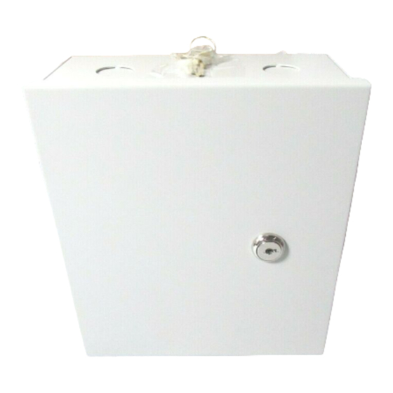
The RM-4T is the board, and the RM-4TE is the RM-CAN enclosure with an
RM-4T mounted in it. The RM-4T can be connected to any Software House
iSTAR series control panel or apC series control panel.
Environmental
Indoor
Storage
Humidity
Electrical
Input
Reader Bus
Output
Reader
LED output control
RM-4T readers must be wired in accordance with the National Electrical Code
(ANSI/NFPA 70), local code.
Hardware Installation
Table 1: Specifications
RM-4T Specifications
32° F to 120° F (0° C to 49° C)
-31° F to 151 ° F (-35 ° C to 66° C)
0 to 85%
12 VDC, 175mA without reader
12 VDC, 550mA with reader
10.9 to 11.18 VDC / 5 VDC
4.0 VDC to 5.25 VDC, 20mA
RM-4T
Version A0
Part Number UM-302
April 2014
1
Advertisement
Table of Contents

Summary of Contents for Software House RM-4T
- Page 1 Part Number UM-302 April 2014 The RM-4T is the board, and the RM-4TE is the RM-CAN enclosure with an RM-4T mounted in it. The RM-4T can be connected to any Software House iSTAR series control panel or apC series control panel.
-
Page 2: Installation
Limit movement during installation to reduce static buildup. Power RM-4T The RM-4T can be powered either from a local, UL listed, access control (UL294) or burglar alarm (UL603), Class 2 power-limited power source with 4-hour standby capability, or from a Software House UL listed, access control (Ul294) or burglar alarm (UL1076) panel which has 4-hour standby capability. -
Page 3: Wall Mount Hardware
Mounting To Mount the RM-4T 1. Ensure that the mounting site has been prepared. The product must be installed indoors. 2. Carefully unpack the RM-4T. Observe the “Static Electricity Precautions” on page 3. Remove the appropriate knockouts. See Figure 1 on page 4. - Page 4 Wiring 5. Install the two bottom mounting screws. Figure 1. Wall Mounting WIRING Figure 2. Wiring...
- Page 5 Table 4: SW3 Switch Configuration Settings SW3 # Function Off (Open) On (Closed) SW3-1 Reader type Magnetic Wiegand SW3-2 LCD Present No LCD NOTE: Not used in the RM-4T. SW3-3 LED Option Normal External Bi-color SW3-4 Tamper Normal Bypass SW3-5 EOL-Termination Not last...
- Page 6 3. Connect P5 input and output wiring, as shown in Figure 2 on page 4 and Figure 3 on page 6. Figure 3. RM-4T Reader Connections Table 5 on page 6 shows the P3 Read Head wiring connections. Table 5: Read Head Wiring Magnetic Stripe (ABA 2)
- Page 7 Readers Table 5: Read Head Wiring (Continued) Magnetic Stripe (ABA 2) Wiegand (Swipe or Proximity) Red LED Red LED Yellow LED Yellow LED Green LED Green LED No connection RS-485 TXD/RXD+ No connection RS-485 TXD/RXD– No connection Read Head Beep Control RM3 LED Connections Wire Black, Red, Yellow, and Green as shown in Figure 4...
-
Page 8: Led Control
LED and Beep Control Reader Wiring Table 6: Reader Wiring Specifications Specifications Signal From Gauge Shielded Max Length Reader RM-4T Wiegand read head 200 ft. (60.96 m) Data 300 ft. (91.4 m) 500 ft. (152.4 m) Reader RM-4T Magnetic read head 10 ft. -
Page 9: Keypad Wiring
2. Attach a local earth ground (18 or 22 gauge) wire to the J5 component on the RM-4T. Multiple RM Bus devices When wiring an RM-4T reader to a bus with multiple devices, such as other RM- 4Ts, I/8s, or R/8s: 1. Attach the shields along the bus together (insulate each connection). Snip off the shield wire at the end of the bus. - Page 10 (bus configuration) Enclosure/cabinet Setting Module To set the module address, set SW1 (16 position rotary switch) to a number from one to eight. Every RM-4T series reader on a bus must have a unique Address and address. EOL Termination To set RS-485 EOL (End of Line) termination, set SW3-5 to the On (closed) position if the module is the last unit on the bus.
- Page 11 NO and NC supervised inputs as close as possible to the switch. Installing the ARM-1 Two ARM-1 relay components can be connected to the RM-4T reader through the P5 connector (Table Relay Module The ARM-1 relay has not been evaluated by UL.
- Page 12 Use rotary switch SW1 to set the reader address. 4. Check the RM-4T for communications to the apC or iSTAR by observing LED2 and LED3. 5. Check the supervised inputs. Configure the inputs on the apC or iSTAR using the C•CURE 9000 Administration application.
-
Page 13: Copyright And Trademarks
Copyright and Trademarks COPYRIGHT AND C•CURE and Software House are registered trademarks of Tyco Security Products. TRADEMARKS The trademarks, logos, and service marks displayed on this document are registered in the United States [or other countries]. Any misuse of the trademarks is strictly prohibited and Tyco will aggressively enforce its intellectual property rights to the fullest extent of the law, including pursuit of criminal prosecution wherever necessary.
Need help?
Do you have a question about the RM-4T and is the answer not in the manual?
Questions and answers