Sony DSX-A410BT Service Manual
Fm/am digital media player
Hide thumbs
Also See for DSX-A410BT:
- Operating instructions manual (236 pages) ,
- Operating instructions manual (84 pages)
Table of Contents
Advertisement
DSX-A410BT/A415BT
SERVICE MANUAL
Ver. 1.1 2017.10
• This model is not equipped with a mechanism deck.
(A415BT)
FOR THE CUSTOMERS IN THE USA. NOT
APPLICABLE IN CANADA, INCLUDING IN THE
PROVINCE OF QUEBEC.
POUR LES CLIENTS AUX ÉTATS-UNIS. NON
APPLICABLE AU CANADA, Y COMPRIS LA
PROVINCE DE QUÉBEC.
AUDIO POWER SPECIFICATIONS
CTA2006 Standard
Power Output: 20 Watts RMS × 4 at 4
Ohms < 1% THD+N
SN Ratio: 80 dBA
(reference: 1 Watt into 4 Ohms)
Tuner section
(A410BT: AEP, UK)
FM
Tuning range:
When [AREA] is set to [EUROPE]:
87.5 MHz – 108.0 MHz
When [AREA] is set to [RUSSIA]:
FM1/FM2: 87.5 MHz – 108.0 MHz
(at 50 kHz step)
FM3: 65 MHz – 74 MHz (at 30 kHz step)
Antenna (aerial) terminal:
External antenna (aerial) connector
Intermediate frequency:
When [AREA] is set to [EUROPE]:
FM CCIR: -1,956.5 kHz to -487.3 kHz and
+500.0 kHz to +2,095.4 kHz
When [AREA] is set to [RUSSIA]:
FM CCIR: -1,956.5 kHz to -487.3 kHz and
+500.0 kHz to +2,095.4 kHz
FM OIRT: -1,815.6 kHz to -943.7 kHz and
+996.6 kHz to +1,776.6 kHz
Usable sensitivity: 7 dBf
Selectivity: 75 dB at 400 kHz
Signal-to-noise ratio: 73 dB
Separation: 50 dB at 1 kHz
Frequency response: 20 Hz – 15,000 Hz
MW/LW
Tuning range:
MW: 531 kHz – 1,602 kHz
LW: 153 kHz – 279 kHz
Antenna (aerial) terminal:
External antenna (aerial) connector
Sensitivity: MW: 26 μV, LW: 50 μV
9-896-416-02
2017J33-1
Sony Video & Sound Products Inc.
©
2017.10
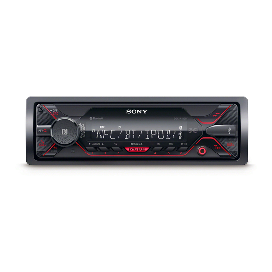
Photo: DSX-A410BT
SPECIFICATIONS
(A410BT: E, AR, IND, AUS)
USB Player section
FM
Interface: USB (Full-speed)
Tuning range:
Maximum current: 1 A
87.5 MHz – 108.0 MHz (at 50 kHz step)
Maximum number of recognizable folders and files:
87.5 MHz – 108.0 MHz (at 100 kHz step)
87.5 MHz – 107.9 MHz (at 200 kHz step)
For Argentine models: 87.5 MHz – 107.9 MHz
Compatible Android Open Accessory protocol
FM tuning step (except for Argentine models):
50 kHz/100 kHz/200 kHz switchable
Corresponding codec:
Antenna (aerial) terminal:
External antenna (aerial) connector
Intermediate frequency:
FM CCIR: -1,956.5 kHz to -487.3 kHz and
+500.0 kHz to +2,095.4 kHz
Usable sensitivity: 7 dBf
Selectivity: 75 dB at 400 kHz
Signal-to-noise ratio: 73 dB
Separation: 50 dB at 1 kHz
Frequency response: 20 Hz – 15,000 Hz
AM
Wireless Communication
Tuning range:
531 kHz – 1,602 kHz (at 9 kHz step)
Communication System:
530 kHz – 1,710 kHz (at 10 kHz step)
For Argentine models: 530 kHz – 1,710 kHz
Output:
AM tuning step (except for Argentine models):
9 kHz/10 kHz switchable
Antenna (aerial) terminal:
External antenna (aerial) connector
Maximum communication range:
Sensitivity: 26 μV
Frequency band:
(A415BT)
FM
Modulation method: FHSS
Tuning range: 87.5 MHz – 107.9 MHz
Compatible BLUETOOTH Profiles*
Antenna (aerial) terminal:
External antenna (aerial) connector
Intermediate frequency:
FM CCIR: -1,956.5 kHz to -487.3 kHz and
+500.0 kHz to +2,095.4 kHz
Usable sensitivity: 7 dBf
Corresponding codec:
Selectivity: 75 dB at 400 kHz
Signal-to-noise ratio: 73 dB
Separation: 50 dB at 1 kHz
*1 The actual range will vary depending on factors such
Frequency response: 20 Hz – 15,000 Hz
AM
Tuning range: 530 kHz – 1,710 kHz
Antenna (aerial) terminal:
*2 BLUETOOTH standard profiles indicate the purpose
External antenna (aerial) connector
Sensitivity: 26 μV
NFC Communication (A410BT: AEP, UK)
Frequency band and maximum power spec
NFC: 13.56 MHz < 60 dBμA/m at 10 m
FM/MW/LW DIGITAL MEDIA PLAYER
Power amplifier section
Output: Speaker outputs
Speaker impedance: 4 Ω – 8 Ω
Maximum power output: 55 W × 4 (at 4 Ω)
Folders (albums): 256
General
Files (tracks) per folder: 256
Outputs:
(AOA): 2.0
MP3 (.mp3)
Bit rate: 8 kbps - 320 kbps (Supports VBR
Inputs:
(Variable Bit Rate))
Sampling rate: 16 kHz - 48 kHz
WMA (.wma)
Bit rate: 32 kbps - 192 kbps (Supports VBR
(Variable Bit Rate))
Sampling rate: 32 kHz, 44.1 kHz, 48 kHz
Power requirements: 12 V DC car battery (negative
FLAC (.flac)
Bit depth: 16 bit, 24 bit
Rated current consumption: 10 A
Sampling rate: 44.1 kHz, 48 kHz
Dimensions:
Mounting dimensions:
BLUETOOTH Standard version 3.0
BLUETOOTH Standard Power Class 2
Mass: Approx. 0.7 kg (1 lb 9 oz)
(radiated -9 dBm) (A410BT: AEP, UK)
Package contents:
(Max. +4 dBm) (A410BT:E, AR, IND, AUS/A415BT)
Line of sight approx. 10 m (33 ft)*
1
2.4 GHz band (2.4000 GHz – 2.4835 GHz)
Design and specifications are subject to change
2
:
without notice.
A2DP (Advanced Audio Distribution Profile) 1.3
AVRCP (Audio Video Remote Control Profile) 1.3
HFP (Handsfree Profile) 1.6
PBAP (Phone Book Access Profile)
SPP (Serial Port Profile)
SBC (.sbc), AAC (.m4a)
as obstacles between devices, magnetic fields
around a microwave oven, static electricity,
reception sensitivity, antenna (aerial)'s performance,
operating system, software application, etc.
of BLUETOOTH communication between devices.
US, CND, E, AR, IND, AUS and PX models
FM/AM DIGITAL MEDIA PLAYER
US Model
Canadian Model
PX Model
DSX-A415BT
AEP Model
UK Model
E Model
Australian Model
DSX-A410BT
Audio outputs terminal (REAR, SUB)
Power antenna (aerial)/Power amplifier control
terminal (REM OUT)
SiriusXM input terminal (A415BT)
Remote controller input terminal
Antenna (aerial) input terminal
AUX input jack (stereo mini jack)
USB port
ground (earth))
Approx. 178 mm × 50 mm × 119 mm
(7
1
/
in × 2 in × 4
3
/
in) (w/h/d)
8
4
Approx. 182 mm × 53 mm × 102 mm
(7
1
/
in × 2
1
/
in × 4
1
/
in) (w/h/d)
4
8
8
Main unit (1)
Remote commander (1): RM-X231 (A410BT:E, AR, IND,
AUS/A415BT)
Parts for installation and connections (1 set)
AEP and UK models
Advertisement
Table of Contents

Related Manuals for Sony DSX-A410BT


Summary of Contents for Sony DSX-A410BT
- Page 1 NFC: 13.56 MHz < 60 dBμA/m at 10 m US, CND, E, AR, IND, AUS and PX models FM/AM DIGITAL MEDIA PLAYER AEP and UK models FM/MW/LW DIGITAL MEDIA PLAYER 9-896-416-02 2017J33-1 Sony Video & Sound Products Inc. © 2017.10...
-
Page 2: Table Of Contents
The Bluetooth® word mark and logos are registered trademarks owned by the Bluetooth SIG, Inc. and 3-3. Sub Panel Complete Assy ..........24 any use of such marks by Sony Corporation is under 3-4. Sub Panel Assy, Microphone .......... 25 license. Other trademarks and trade names are 3-5. -
Page 3: Servicing Notes
350 °C. Part No. Destination Caution: The printed pattern (copper foil) may peel away if 4-698-228-0[] DSX-A410BT: E, AUS models (E) the heated tip is applied for too long, so be careful! 4-698-229-0[] DSX-A410BT: AR model (AR) • Strong viscosity... - Page 4 Note 3: Refer to the following “1-3. Entering the Destination Code” for • Method of operation by remote commander operation method. (DSX-A410BT: E, AR, IND, AUS/DSX-A415BT) Note: The model to which the remote commander is not attached can Destination code also be operated by using the optional remote commander.
- Page 5 DSX-A410BT/A415BT Ver. 1.1 1-4. Destination Code NOTE OF REPLACING THE ANT001, CP001, IC001, IC602 AND IC1301 ON THE MAIN BOARD Model Destination OP5 OP4 OP3 OP2 OP1 OP0 ANT001, CP001, IC001, IC602 and IC1301 on the MAIN board AEP, UK cannot replace with single.
- Page 6 DSX-A410BT/A415BT OPERATION CHECK OF THE NFC AFTER COMPLET- IMPORTANT NOTE OF INITIALIZING ING THE REPAIRS The purpose of “Bluetooth Initialize” is to initialize the Bluetooth After completing the repairs of this unit, follow the procedure below connection history (HF/Audio Streaming). (To delete the device to check normal operation of the NFC.
- Page 7 Bluetooth compatible smartphone or cellular phone 2. Search for the distance of this unit and the Bluetooth device • Bluetooth audio devices (SONY NWZ-A826, or select from (smartphone or cellular phone) about 5 m apart. connectable smartphone, cellular phones or audio devices list) Confi...
- Page 8 DSX-A410BT/A415BT BLUETOOTH INFORMATION WRITING METHOD 1. Installing the NFC Tag Data Writing Application for When the following parts are replaced, the writing of Bluetooth the Servicing information is necessary. Install the NFC Tag Data Writing Application on the smart- phone for writing of Bluetooth information.
- Page 9 DSX-A410BT/A415BT • Checking the Version of the NFC Tag Data Writing 2. Writing the NFC Tag Data Application Write the NFC tag data (Bluetooth information) to the NFC mod- ule in the knob (VOL) assy (Ref. No. NFC1). Procedure: 1. Start the NFC Tag Data Writing Application on the smart- Procedure: phone.
- Page 10 DSX-A410BT/A415BT How to display on the liquid crystal display by the 5. Input the Bluetooth Local Name (BL_NAME). Tap the “List” on the screen of the smartphone and select the test mode: model name of the this unit. If there is not model name of the...
- Page 11 DSX-A410BT/A415BT 9. Check that “Completed!” is displayed on the screen of the 16. Check that “Completed!” is displayed on the screen of the smartphone. smartphone. Note 2: When “Completed!” is not displayed on the screen of the smart- Note 3: When “Completed!” is not displayed on the screen of the smart- phone, refer to “3.
- Page 12 DSX-A410BT/A415BT 3. Error Display How to display on the liquid crystal display by the When the writing of the NFC tag data has failed, “Error” is dis- test mode: played on the screen of the smartphone. 1 In the state of source off (the clock is displayed on the When “Error”...
- Page 13 DSX-A410BT/A415BT 5. The Factor that One Touch Connection is Impossible The four following factors are considered as the factor that one touch connection is impossible. Guess and check the defective factor by each checking result. Note: The four following factors are examples.
- Page 14 DSX-A410BT/A415BT MEMO...
- Page 15 DSX-A410BT/A415BT • Please cut out along the dotted line and use it. Notice about the serial number change on the back side of Notice about the serial number change on the back side of the front panel: the front panel:...
- Page 16 DSX-A410BT/A415BT MEMO...
-
Page 17: General
DSX-A410BT/A415BT SECTION 2 This section is extracted GENERAL from operating instruction. (DSX-A410BT: AEP, UK) Connection Connection/Installation Subwoofer* Cautions Run all ground (earth) leads to a common ground (earth) point. Do not get the leads trapped under a screw, or Power amplifier* caught in moving parts (e.g., seat railing). - Page 18 In such a case, covered in this manual, consult the car dealer. consult your nearest Sony dealer. Using the wired remote control To enable the wired remote control, set [STR CONTROL] in [SET STEERING] to [PRESET] (page 19).
- Page 19 DSX-A410BT/A415BT Ver. 1.1 (DSX-A410BT: E, AR, IND, AUS) Connection Connection/Installation Subwoofer* Cautions Run all ground (earth) leads to a common ground (earth) point. Do not get the leads trapped under a screw, or Power amplifier* caught in moving parts (e.g., seat railing).
- Page 20 DSX-A410BT/A415BT Ver. 1.1 (DSX-A410BT: E, AR, IND, AUS) Mounting the unit in a Japanese car Power connection diagram (Argentine Installation You may not be able to install this unit in some models only) makes of Japanese cars. In such a case, consult your Sony dealer.
- Page 21 DSX-A410BT/A415BT Ver. 1.1 (DSX-A415BT) Connection Connection/Installation Subwoofer* Cautions Run all ground (earth) leads to a common ground (earth) point. Do not get the leads trapped under a screw, or Power amplifier* caught in moving parts (e.g., seat railing). Before making connections, turn the car ignition...
- Page 22 If the fuse blows, check the power connection and replace the fuse. If the fuse blows again after replacement, there may be an internal malfunction. In such a case, consult your nearest Sony dealer.
-
Page 23: Disassembly
DSX-A410BT/A415BT SECTION 3 DISASSEMBLY • This set can be disassembled in the order shown below. 3-1. DISASSEMBLY FLOW FRONT PANEL OVERALL ASSY Note: Illustration of disassembly is omitted. 3-2. MINI FUSE (BLADE TYPE), COVER (Page 23) 3-3. SUB PANEL COMPLETE ASSY (Page 24) 3-4. -
Page 24: Sub Panel Complete Assy
DSX-A410BT/A415BT 3-3. SUB PANEL COMPLETE ASSY 2 two claws (See Fig. A) Insert the connector straight into the interior. 2 two claws 1 microphone wire There is a possibility that using this unit (See Fig. A) connector without the connector correctly installed will (CN1004) damage it. -
Page 25: Sub Panel Assy, Microphone
DSX-A410BT/A415BT 3-4. SUB PANEL ASSY, MICROPHONE top side filament tape rear side guide line (sub material) top side 1 filament tape (sub material) 5 sub panel assy microphone microphone hole boss 3 claw wire – – sub panel assy 4 microphone block... -
Page 26: Test Mode
DSX-A410BT/A415BT SECTION 4 TEST MODE SETTING THE TEST MODE Setting method: 1. In the state of source off (the clock is displayed on the liquid crystal display), enter the test mode by pressing the buttons in order of the [ 4] t [MIC 5] t [ V ALBUM 1] (press only the [ V ALBUM 1] button for two seconds). -
Page 27: Diagrams
DSX-A410BT/A415BT Ver. 1.1 SECTION 5 DIAGRAMS 5-1. BLOCK DIAGRAM - MAIN Section - CENTER VOLTAGE ILL_+B GENERATOR IC402 (1/2) KEY BOARD (1/2) 72 UDP1 D– 71 UDM1 J400 DACOUTL 99 LVRIN LINE AMP LROUT IC401 REAR (A410BT) DACOUTS 10 SWIN... -
Page 28: Block Diagram - Panel/Power Supply Section
DSX-A410BT/A415BT Ver. 1.1 5-2. BLOCK DIAGRAM - PANEL/POWER SUPPLY Section - THIS NOTE IS COMMON FOR PRINTED WIRING BOARDS AND SCHEMATIC DIAGRAMS. (In addition to this, the necessary note is printed in each block.) SYSTEM CONTROLLER REGULATOR VDD_3.3V IC501 (2/2) -
Page 29: Schematic Diagram - Main Board (1/3)
DSX-A410BT/A415BT Ver. 1.1 5-3. SCHEMATIC DIAGRAM - MAIN Board (1/3) - • See page 28 for Waveforms. • See page 34 for IC Block Diagrams. • See page 35 for IC Pin Function Description. MAIN BOARD (1/3) >002S MAIN BOARD... -
Page 30: Schematic Diagram - Main Board (2/3)
DSX-A410BT/A415BT Ver. 1.1 5-4. SCHEMATIC DIAGRAM - MAIN Board (2/3) - • See page 28 for Waveforms. • See page 34 for IC Block Diagrams. • See page 35 for IC Pin Function Description. MAIN BOARD (2/3) >003S MAIN (Page 31) -
Page 31: Schematic Diagram - Main Board (3/3)
DSX-A410BT/A415BT Ver. 1.1 5-5. SCHEMATIC DIAGRAM - MAIN Board (3/3) - • See page 28 for Waveforms. • See page 34 for IC Block Diagrams. (A410BT: E, IND, AUS/A415BT) MAIN BOARD (3/3) Q407 Q408 DTA014EEBTL DTA014EEBTL REAR RCH (+) IC304 IC201 13.6... -
Page 32: Main Board (Component Side)
DSX-A410BT/A415BT Ver. 1.1 5-6. PRINTED WIRING BOARD - MAIN Board (Component Side) - • : Uses unleaded solder. MAIN BOARD (COMPONENT SIDE) D400 R400 C305 C321 C206 (A415BT) F802 D1322 D1319 R435 R436 R438 C404 C406 C413 C418 IC401 C426... -
Page 33: Printed Wiring Board - Main Board (Conductor Side)
DSX-A410BT/A415BT Ver. 1.1 5-7. PRINTED WIRING BOARD - MAIN Board (Conductor Side) - • : Uses unleaded solder. (A415BT) (FRONT VIEW) J400 CN301 REAR (A410BT: E, IND, AUS/A415BT) MAIN BOARD (CONDUCTOR SIDE) AUDIO OUT AUDIO OUT J801 (REMOTE IN) REAR LCH (+) - Page 34 DSX-A410BT/A415BT • IC Block Diagrams – MAIN Board – IC001 SDP2014HN/V102 IC1003 NJM2781RB1 NOISE 1 8 GND 32 31 27 26 REG 2 REGULATOR STBY 3 7 V+ VDDA_IFADC 1 DIGITAL CONTROL DIGITAL IN+ 4 XTAL 6 OUT VSSA_IFADC 2...
- Page 35 DSX-A410BT/A415BT Ver. 1.1 • IC Pin Function Description MAIN BOARD IC501 LC88FC3K0AF2337-ENG (SYSTEM CONTROLLER) Pin No. Pin Name Description 1 to 3 Not used FLASH_RW Debug communication terminal Not used System reset signal input terminal “L”: reset RESET For several hundreds msec. after the power supply rises, “L” is input, then it change to “H”...
- Page 36 DSX-A410BT/A415BT Pin No. Pin Name Description SIRCS Remote control signal input from the front panel block Not used 66, 67 DEBUG_6, DEBUG_7 Debug test terminal Not used BEEP Beep sound signal output to the power amplifi er Not used RC_STR_SEL...
- Page 37 DSX-A410BT/A415BT Ver. 1.1 MAIN BOARD IC601 LC786823E-6E14-3H (USB CONTROLLER, INPUT SELECTOR, AUDIO DSP, ELECTRICAL VOLUME) Pin No. Pin Name Description Not used AVDD1 Power supply terminal (+3.3V) (for analog system) AVSS1 Ground terminal (for analog system) External capacitor connection terminal for audio D/A converter and electrical volume reference...
- Page 38 DSX-A410BT/A415BT Pin No. Pin Name Description CD_BUSYB Not used LACK Not used Not used DATA Not used MCLK Not used USB_IN USB device detection signal output to the system controller “L”: USB device is connected Not used GP46 Not used...
-
Page 39: Exploded View
DSX-A410BT/A415BT Ver. 1.1 SECTION 6 EXPLODED VIEW Note: • -XX and -X mean standardized parts, so • The mechanical parts with no reference they may have some difference from the number in the exploded views are not sup- original one. -
Page 40: Electrical Parts List
DSX-A410BT/A415BT Ver. 1.1 SECTION 7 MAIN ELECTRICAL PARTS LIST Note: • Due to standardization, replacements in • CAPACITORS When indicating parts by reference num- uF: μF the parts list may be different from the ber, please include the board name. - Page 41 DSX-A410BT/A415BT Ver. 1.1 MAIN Ref. No. Part No. Description Remark Ref. No. Part No. Description Remark C413 1-164-315-91 CERAMIC CHIP 470PF C640 1-165-908-11 CERAMIC CHIP 1uF C416 1-100-966-91 CERAMIC CHIP 10uF C641 1-118-386-11 CERAMIC CHIP 0.1uF C418 1-118-047-11 CERAMIC CHIP 10uF...
- Page 42 DSX-A410BT/A415BT Ver. 1.1 MAIN Ref. No. Part No. Description Remark Ref. No. Part No. Description Remark * C1573 1-116-720-11 CERAMIC CHIP 10uF 6.3V IC401 6-721-638-01 IC NJM8065RB1-TE1 (A415BT) C1580 1-118-418-11 CERAMIC CHIP 22uF 6.3V IC402 6-721-638-01 IC NJM8065RB1-TE1 IC403 6-712-391-01 IC TC74VHC4066AFK (EK) (A415BT) <...
- Page 43 DSX-A410BT/A415BT Ver. 1.1 MAIN Ref. No. Part No. Description Remark Ref. No. Part No. Description Remark R107 1-216-049-11 METAL CHIP 1/8W R437 1-216-797-11 METAL CHIP 1/10W (A410BT) R438 1-218-990-81 SHORT CHIP R109 1-216-827-11 METAL CHIP 3.3K 1/10W R439 1-218-966-11 METAL CHIP...
- Page 44 DSX-A410BT/A415BT Ver. 1.1 MAIN Ref. No. Part No. Description Remark Ref. No. Part No. Description Remark R569 1-218-941-81 METAL CHIP 1/16W R1311 1-216-821-11 METAL CHIP 1/10W R572 1-218-941-81 METAL CHIP 1/16W R1312 1-216-821-11 METAL CHIP 1/10W R573 1-218-941-81 METAL CHIP...
- Page 45 DSX-A410BT/A415BT Ver. 1.1 Ref. No. Part No. Description Remark Ref. No. Part No. Description Remark MISCELLANEOUS PARTS FOR INSTALLATION AND CONNECTIONS ************** ************************************** A-2187-991-A PANEL (SV) ASSY, FRONT X-2583-962-1 FRAME ASSY, FITTING (Bracket) (Including Serial number label) 4-276-003-03 KEY (FRAME) (Release key) (1 piece)
- Page 46 Description of Revision 2017.07 2017.10 Addition of E, AR, IND and AUS models (DSX-A410BT) Addition of DSX-A415BT How to search for a contact point of signal lines or the like in DIAGRAMS SECTION If a contact point of a BLOCK DIAGRAM, PRINTED WIRING BOARD or SCHEMATIC DIAGRAM is shown in a different page, use the PDF fi...
Need help?
Do you have a question about the DSX-A410BT and is the answer not in the manual?
Questions and answers