Table of Contents
Advertisement
Advertisement
Table of Contents

Subscribe to Our Youtube Channel
Summary of Contents for Circo 8200 Series
- Page 1 Hardware Installation Guide for Cisco 8200 Series Routers First Published: 2020-08-15 Last Modified: 2022-09-22 Americas Headquarters Cisco Systems, Inc. 170 West Tasman Drive San Jose, CA 95134-1706 http://www.cisco.com Tel: 408 526-4000 800 553-NETS (6387) Fax: 408 527-0883...
- Page 2 © 2020 Cisco Systems, Inc. All rights reserved.
-
Page 3: Table Of Contents
Rack-Mount the Chassis in a 4-Post Rack Rack-Mount the Chassis in a 2-Post Rack Installing a Cable Management Bracket Install the Air Filter Install the Air Filter on the Port Side Inlet Hardware Installation Guide for Cisco 8200 Series Routers... - Page 4 C H A P T E R 5 Replace Chassis Components Replace the Latched Fan Modules Replace Fan Modules for Cisco 8202 Router Replace Fan Modules for Cisco 8202-32FH-M Router Replace Power Supply Replace Power Supply Remove SSD Card Hardware Installation Guide for Cisco 8200 Series Routers...
- Page 5 Contents C H A P T E R 6 LEDs Chassis LEDs Fan Tray LED Power Supply LEDs Port Status LEDs Hardware Installation Guide for Cisco 8200 Series Routers...
- Page 6 Contents Hardware Installation Guide for Cisco 8200 Series Routers...
-
Page 7: Cisco 8200 Series Routers Overview
The 8202-32FH-MO variant supports Cisco-qualified open-source network operating systems, such as SONiC (Software for Open Networking in the Cloud). Hardware Installation Guide for Cisco 8200 Series Routers... - Page 8 Supported ports include 32 x 400G QSFP-DD. The Cisco 8200 Series Routers utilizes Cisco’s new Router-on-Chip (RoC) model to deliver full routing functionality with a single ASIC per router. The RoC architecture is distinguished from System-on-Chip (SoC) switches by supporting large forwarding tables, deep buffers, more flexible packet operations, and enhanced programmability.
-
Page 9: Prepare For Installation
Before you perform any procedure in this document, review the safety guidelines in this section to avoid injuring yourself or damaging the equipment. The following guidelines are for your safety and to protect the equipment. Because the guidelines do not include all hazards, be constantly alert. Hardware Installation Guide for Cisco 8200 Series Routers... -
Page 10: Compliance And Safety Information
Read the installation instructions before using, installing, or connecting the system to the power source. Warning Statement 1040 Product Disposal Ultimate disposal of this product should be handled according to all national laws and regulations. Hardware Installation Guide for Cisco 8200 Series Routers... - Page 11 (EMI) that might disrupt other equipment, and they direct the flow of cooling air through the chassis. Do not operate the system unless all cards, faceplates, front covers, and rear covers are in place. Hardware Installation Guide for Cisco 8200 Series Routers...
-
Page 12: Laser Safety
(ESD) precautions can result in intermittent or complete component failures. To minimize the potential for ESD damage, always use an ESD-preventive antistatic wrist strap (or ankle strap) and ensure that it makes adequate skin contact. Hardware Installation Guide for Cisco 8200 Series Routers... -
Page 13: Cautions And Regulatory Compliance Statements For Nebs
The battery return conductor of this equipment shall be treated as (DC-I). Statement 7016 Warning This equipment is suitable for installation in Network Telecommunications Facilities. Statement 8015 Warning This equipment is suitable for installation in locations where the NEC applies. Statement 8016 Hardware Installation Guide for Cisco 8200 Series Routers... -
Page 14: Installation Guidelines
• Number 1 and number 2 Phillips screwdrivers with torque capability to rack-mount the chassis. • 3/16-inch flat-blade screwdriver. • Tape measure and level. • ESD wrist strap or other grounding device. • Antistatic mat or antistatic foam. • Two-hole ground lug (1). Hardware Installation Guide for Cisco 8200 Series Routers... -
Page 15: Router Accessory Kit
40 in. (1016 mm) Router Air Filter Kit Note Air filters are for single time use only. The following table contains the air filter PIDs and the items description for the Cisco 8202 series chassis: Hardware Installation Guide for Cisco 8200 Series Routers... -
Page 16: Prepare Your Location
Unless specified otherwise, the image is only for representational purposes. The rack's actual appearance and size may vary. Note This image is only for representational purposes. Your grounding requirement depends on your building. Hardware Installation Guide for Cisco 8200 Series Routers... -
Page 17: Prepare Yourself
The figures show how to cuff the ESD strap around the wrist and the ground cord that connects the cuff to the ground. ESD wrist straps are the primary means of controlling static charge on personnel. Hardware Installation Guide for Cisco 8200 Series Routers... -
Page 18: Prepare Rack For Chassis Installation
Figure 2: Wearing the ESD Strap Prepare Rack for Chassis Installation Install the Cisco 8200 Series Routers on a standard 19 inch, Electronic Industries Alliance (EIA) rack with mounting rails that conform to English universal hole spacing according to Section 1 of the ANSI/EIA-310-D-1992 standard. - Page 19 Make sure that floor mounting bolts are accessible, especially if annual retorquing of bolts is required. Ensure that the rack in which the chassis is being installed is grounded to earth ground. Note Hardware Installation Guide for Cisco 8200 Series Routers...
-
Page 20: Clearance Requirements
(8201-32FH and 8021-24H8FH routers) 23.6 in. (59.94 cm) Chassis depth. (Other routers) 20.01 in. (50.82 cm) Chassis depth. Hardware Installation Guide for Cisco 8200 Series Routers... -
Page 21: Installing The Chassis
• When mounting this unit in a partially filled rack, load the rack from the bottom to the top with the heaviest component at the bottom of the rack. • If the rack is provided with stabilizing devices, install the stabilizers before mounting or servicing the unit in the rack. Hardware Installation Guide for Cisco 8200 Series Routers... -
Page 22: Rack-Mount The Chassis In A 4-Post Rack
• If the router has port-side exhaust modules (fan modules and power modules with blue coloring), position the router so that the fan and power supply modules are in the cold aisle. Hardware Installation Guide for Cisco 8200 Series Routers... - Page 23 The holes that you use depend on which end of your chassis is located in the cold aisle. Figure 5: Rack-Mount Brackets on Cisco 8201 Router Port-Side Intake Hardware Installation Guide for Cisco 8200 Series Routers...
- Page 24 Rack-Mount the Chassis in a 4-Post Rack Figure 6: Rack-Mount Brackets on Cisco 8201 Router Port-Side Exhaust Rack-mount brackets Rack-mount guide rails M4 x 6mm Phillips Remove grounding cover flat-head screws label Rack-mount guide Grounding plate Hardware Installation Guide for Cisco 8200 Series Routers...
- Page 25 Installing the Chassis Rack-Mount the Chassis in a 4-Post Rack Figure 7: Rack-Mount Brackets (8K-2RU-KIT-S) on Cisco 8202-32FH-M Router Port-Side Intake Figure 8: Rack-Mount Brackets (8K-2RU-KIT-L) on Cisco 8202-32FH-M Router Port-Side Intake Hardware Installation Guide for Cisco 8200 Series Routers...
- Page 26 • 8K-2RU-KIT-S - Used for rack depth of 23" to 30" • 8K-2RU-KIT-L - Used for rack depth of 30" to 40" Figure 9: Rack-Mount Brackets on Cisco 8202 Router Port-Side Intake Hardware Installation Guide for Cisco 8200 Series Routers...
- Page 27 Figure 10: Rack-Mount Brackets on Cisco 8202 Router Port-Side Exhaust Rack-mount brackets Rack-mount guide M4 x 6mm Phillips Rack-mount guide rails flat-head screws Figure 11: Rack-Mount Brackets on Cisco 8201-32FH or Cisco 8201-24H8FH Router Port-Side Intake Hardware Installation Guide for Cisco 8200 Series Routers...
- Page 28 Holding the chassis level, insert two screws (12-24 or 10-32, depending on the rack type) through the holes in each of the rack-mount brackets and into the cage nuts or threaded holes in the rack-mounting rail. Hardware Installation Guide for Cisco 8200 Series Routers...
-
Page 29: Rack-Mount The Chassis In A 2-Post Rack
Use four M4 flat-head screws with 13.25 in-lbs (1.5 N-m) torque value to attach the bracket to the chassis. Hardware Installation Guide for Cisco 8200 Series Routers... - Page 30 Installing the Chassis Rack-Mount the Chassis in a 2-Post Rack Figure 13: Rack-Mount Brackets on Cisco 8201 Router Port-Side Intake Hardware Installation Guide for Cisco 8200 Series Routers...
- Page 31 Figure 14: Figure 6: Rack-Mount Brackets on Cisco 8201 Router Port-Side Exhaust Rack-mount brackets Ground plate mount location M4 x 6-mm Phillips M4 x 6-mm Phillips flat-head screws flat-head screws Grounding plate Hardware Installation Guide for Cisco 8200 Series Routers...
- Page 32 Installing the Chassis Rack-Mount the Chassis in a 2-Post Rack Figure 15: Rack-Mount Brackets on Cisco 8202 Router Port-Side Intake Hardware Installation Guide for Cisco 8200 Series Routers...
- Page 33 Installing the Chassis Rack-Mount the Chassis in a 2-Post Rack Figure 16: Rack-Mount Brackets on Cisco 8202 Router Port-Side Exhaust Rack-mount brackets M4 x 6-mm Phillips flat-head screws Hardware Installation Guide for Cisco 8200 Series Routers...
- Page 34 Figure 18: Rack-Mount Brackets on Cisco 8201-32FH or Cisco 8201-24H8FH Router Port-Side Exhaust Grounding plate M4 x 6-mm Phillips flat-head screws Ground plate mount Rack-mount brackets location M4 x 6-mm Phillips flat-head screws Hardware Installation Guide for Cisco 8200 Series Routers...
- Page 35 2. Attach the rear rack mount bracket and rail slider on both sides of the chassis (marked as 2 in the Rack-Mount Brackets on Cisco 8202-32FH-M Router Port-Side Intake image). You must first slide the rail into rear rack mount and then fix them in the assembled condition to the chassis. Hardware Installation Guide for Cisco 8200 Series Routers...
-
Page 36: Installing A Cable Management Bracket
• The cable management brackets for Cisco 8202-32FH-M chassis supports only optics cables. Step 1 Attach an ESD-preventive wrist or ankle strap and follow its instructions for use. Step 2 Align the cable-management bracket with the three alignment pins on the rack-mount bracket. Hardware Installation Guide for Cisco 8200 Series Routers... -
Page 37: Install The Air Filter
Connect all the cables to the intended ports and pass them through the cable management bracket in an organized manner. Install the Air Filter The Cisco 8200 series routers offer the following optional air filters: Router Filter Kit (port-side intake) -
Page 38: Install The Air Filter On The Port Side Inlet
Bottom Air Filter Section Step 2 Place the bottom air filter section along the bottom port-side of the chassis and secure it with the two screws at the lower left and right. Hardware Installation Guide for Cisco 8200 Series Routers... -
Page 39: Install The Air Filter On The Port Side Exhaust
Install the side filter extension and tighten the 2 screws (1 to the chassis and 1 to the main air filter). Install the Air Filter on the Port Side Inlet for Cisco 8202-32FH-M Chassis If the air filter on the port-side inlet needs replacement, follow this procedure. Hardware Installation Guide for Cisco 8200 Series Routers... -
Page 40: Ground The Chassis
Statement 1252 Equipment Grounding This equipment must be grounded. To reduce the risk of electric shock, the power cord, plug, or combination must be connected to a properly grounded electrode, outlet, or terminal. Hardware Installation Guide for Cisco 8200 Series Routers... - Page 41 Use the crimping tool to secure the grounding cable in the grounding lug. Step 4 Attach the ground cable: • Attach one end of the shelf ground cable (#6 AWG cable) to the grounding plate using the specified dual-hole lug connector. Hardware Installation Guide for Cisco 8200 Series Routers...
- Page 42 Installing the Chassis Ground the Chassis Figure 24: Cisco 8201 Router Ground Lug Hardware Installation Guide for Cisco 8200 Series Routers...
- Page 43 Installing the Chassis Ground the Chassis Figure 25: Cisco 8202 Router Ground Lug Figure 26: Cisco 8201-32FH or Cisco 8201-24H8FH Ground Lug Grounding lug M4 x 6mm pan-head screws Hardware Installation Guide for Cisco 8200 Series Routers...
-
Page 44: Power Supply Unit Input And Output Ranges
Only trained and qualified personnel should be allowed to install, replace, or service this equipment. Warning Statement 1090 Installation by Skilled Person Only a skilled person should be allowed to install, replace, or service this equipment. See statement 1089 for the definition of a skilled person. Hardware Installation Guide for Cisco 8200 Series Routers... - Page 45 100V -127V AC 1000W PSU1.4KW-ACPE Cisco 8202 For low line Cisco 8201-32FH applications Cisco 8201-24H8FH PSU1.4KW-ACPI Cisco 8201 200V -240V AC 1450W PSU1.4KW-ACPE Cisco 8202 For high line Cisco 8201-32FH applications Cisco 8201-24H8FH Hardware Installation Guide for Cisco 8200 Series Routers...
- Page 46 For AC high line Cisco 8202 applications Cisco 8201-32FH Cisco 8201-24H8FH Cisco 8202-32FH-M PSU2KW-HVPI Cisco 8201 90V AC - 140V 1000W For AC low line Cisco 8202 applications Cisco 8201-32FH Cisco 8201-24H8FH Cisco 8202-32FH-M Hardware Installation Guide for Cisco 8200 Series Routers...
-
Page 47: Connect Ac Power To The Chassis
Place the cable through the opening in the cable clamp. Step 4 Slide the cable clamp toward the plug. Step 5 Close the cable clamp on the shoulder of the power cable to secure the power cable. Hardware Installation Guide for Cisco 8200 Series Routers... -
Page 48: Ac-Input Power Cord Options
Cable clamp AC power cable AC-Input Power Cord Options This table summarises the input and output power ranges for PSU high line applications: Table 8: AC-Input Power Cord Options for Cisco 8200 Series Router Locale Part Number Length Power Cord Rating... - Page 49 13A, 250 VAC C14-C15 Connectors C9600 AC IEC C15 to NEMA L6-20P cable CAB-AC-2KW-CBL 14 ft (4.26 13A, 250 VAC Table 9: High-Voltage Input Power Cord Options for Cisco 8200 Series Router Locale Part Number Length Power Cord Rating Argentina CAB-AC-16A-SG-AR 14 ft (4.26...
- Page 50 CAB-HV-25A-SG-IN2 14 ft (4.26 20A, 300 VAC/500 source plug AC Power Cord Illustrations for Cisco 8200 Series Router This section contains the AC power cord illustrations, as described in the above table. Hardware Installation Guide for Cisco 8200 Series Routers...
- Page 51 Installing the Chassis AC-Input Power Cord Options Figure 29: CAB-AC-16A-SG-AR Power Cord Figure 30: CAB-AC-16A-SG-AZ Power Cord Figure 31: CAB-AC-16A-SG-BR Power Cord Hardware Installation Guide for Cisco 8200 Series Routers...
- Page 52 Installing the Chassis AC-Input Power Cord Options Figure 32: CAB-AC-16A-SG-CH Power Cord Figure 33: CAB-AC-16A-SG-EU Power Cord Figure 34: CAB-AC-16A-SG-IND Power Cord Hardware Installation Guide for Cisco 8200 Series Routers...
- Page 53 Installing the Chassis AC-Input Power Cord Options Figure 35: CAB-AC-16A-SG-IN Power Cord Figure 36: CAB-AC-16A-SG-IS Power Cord Figure 37: CAB-AC-16A-SG-IT Power Cord Hardware Installation Guide for Cisco 8200 Series Routers...
- Page 54 Installing the Chassis AC-Input Power Cord Options Figure 38: CAB-AC-16A-SG-JPN Power Cord Figure 39: CAB-AC-16A-SG-SA Power Cord Figure 40: CAB-AC-16A-SG-SW Power Cord Hardware Installation Guide for Cisco 8200 Series Routers...
- Page 55 Installing the Chassis AC-Input Power Cord Options Figure 41: CAB-AC-16A-SG-UK Power Cord Figure 42: CAB-AC-20A-SG-US Power Cord Figure 43: CAB-AC-20A-SG-US1 Power Cord Hardware Installation Guide for Cisco 8200 Series Routers...
- Page 56 Installing the Chassis AC-Input Power Cord Options Figure 44: CAB-AC-20A-SG-US2 Power Cord Figure 45: CAB-AC-20A-SG-US3 Power Cord Figure 46: CAB-AC-20A-SG-US4 Power Cord Hardware Installation Guide for Cisco 8200 Series Routers...
- Page 57 Installing the Chassis AC-Input Power Cord Options Figure 47: CAB-AC-20A-SG-C20 Power Cord Figure 48: CAB-HV-25A-SG-US2 Power Cord Figure 49: CAB-HV-25A-SG-IN2 Power Cord Hardware Installation Guide for Cisco 8200 Series Routers...
-
Page 58: Connect Dc Power To The Chassis
Dress the power according to local practice. Step 4 Connect the office battery and return cables according to the fuse panel engineering specifications. Step 5 Insert the DC connector into the DC receptacle on the power supply. Hardware Installation Guide for Cisco 8200 Series Routers... - Page 59 Figure 51: Connecting DC Power - Cisco 8202 Fixed Port Router DC power cable Step 6 Ensure that the locking mechanism has engaged to secure the cable. Step 7 Turn on the circuit breaker at the power source. Hardware Installation Guide for Cisco 8200 Series Routers...
- Page 60 Installing the Chassis Connect DC Power to the Chassis Hardware Installation Guide for Cisco 8200 Series Routers...
-
Page 61: Connect Router To The Network
• Clean the connectors regularly; the required frequency of cleaning depends upon the environment. In addition, clean connectors when they are exposed to dust or accidentally touched. Both wet and dry cleaning techniques can be effective; refer to your site's fiber-optic connection cleaning procedures. Hardware Installation Guide for Cisco 8200 Series Routers... -
Page 62: Interfaces And Port Description
100G ports (Port 24 to Mini coax connector for 1 Port 35) support 100G and PPS, input, and output. 40G. Ports 24, 26, 28, 30, 32, and 34 support 4x10G and 4x50G via breakout cable. Hardware Installation Guide for Cisco 8200 Series Routers... - Page 63 Figure 53: Cisco 8201 Fixed Port Router - Rear View Console Port 1000BASE-T Management and BMC (Baseboard Management Controller) Port 10GBASE-T Control USB Port Type-A Plane Expansion Port RJ-45 connector for Time-of-Day (TOD) interface, input, and output Hardware Installation Guide for Cisco 8200 Series Routers...
- Page 64 400G Ports. All 400G port 1.0/2.3 50 ohm connector support breakout for 10MHz, input, and operation. output. 100G ports and even ports 1.0/2.3 50 ohm connector support 4x10G and 4x50G for 1 PPS, input, and output. Hardware Installation Guide for Cisco 8200 Series Routers...
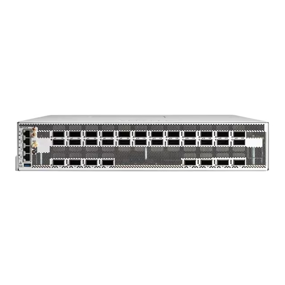
- Page 65 Figure 55: Cisco 8202 Fixed Port Router - Rear View Console Port 1000BASE-T Management and BMC (Baseboard Management Controller) Port 10GBASE-T Control USB Port Type-A Plane Expansion Port RJ-45 connector for Time-of-Day (TOD) interface, input, and output Hardware Installation Guide for Cisco 8200 Series Routers...
- Page 66 Interfaces and Port Description Figure 56: Cisco 8201-32FH Router - Front View 400G QSFP-DD Ports. All 400G port support breakout operation. Figure 57: Cisco 8201-32FH Router - Rear View Power Supply Fans Hardware Installation Guide for Cisco 8200 Series Routers...
- Page 67 Connect Router to the Network Interfaces and Port Description Figure 58: Cisco 8202-32FH-M Router - Front View 400G QSFP-DD Ports. All 400G port support breakout operation. Figure 59: Cisco 8201-24H8FH Router - Front View Hardware Installation Guide for Cisco 8200 Series Routers...
- Page 68 Plane Expansion Port RJ-45 connector for 1000BASE-T Time-of-Day (TOD) Management and BMC interface, input, and (Baseboard Management output. Controller) Port USB Port Type-A. Figure 60: Cisco 8201-24H8FH Router - Rear View Power Supply Fans Hardware Installation Guide for Cisco 8200 Series Routers...
-
Page 69: Connecting A Console To The Router
• An RJ45 rollover cable and a DB9F/RJ45 adapter. • Network cabling should already be routed to the location of the installed router. Step 1 Configure the console device to match the following default port characteristics: Hardware Installation Guide for Cisco 8200 Series Routers... -
Page 70: Create The Initial Router Configuration
• A console device must be connected with the router. • The router must be connected to a power source. • Determine the IP address and netmask that is needed for the Management interfaces: MgmtEth0/RP0/CPU0/0 Hardware Installation Guide for Cisco 8200 Series Routers... - Page 71 When you enter a strong password, the software asks you to confirm the password. Step 4 Reenter the password. When you enter the same password, the software accepts the password. Hardware Installation Guide for Cisco 8200 Series Routers...
-
Page 72: Connect The Management Interface
You are ready to connect the interface ports to the network. Installing Dust Caps Install dust caps to protect unused or unconnected optical ports on the Cisco 8200 Series Routers. The following list provides the product IDs (PIDs) for the dust caps that are available for each port type:... -
Page 73: Install And Remove Transceiver Modules
Figure 61: 400-Gigabit QSFP-DD Transceiver Module Pull-tab QSFP-DD transceiver body Electrical connection to the module circuitry Warning Statement 1079 Hot Surface This icon is a hot surface warning. Use precaution when working near the hot surface. Hardware Installation Guide for Cisco 8200 Series Routers... -
Page 74: Required Tools And Equipment
Table 10: Supported Ports and Operating Temperature of QDD-400G-ZR-S and QDD-400G-ZRP-S Optical Modules Fixed-Port Routers Port Side Intake Fans and Port Side Exhaust Fans and Port Side Intake Power Supplies Power Supplies Operating Temperature Hardware Installation Guide for Cisco 8200 Series Routers... - Page 75 Hold the transceiver by the pull-tab so that the identifier label is on the top. Step 5 Align the transceiver module in front of the module’s transceiver socket opening and carefully slide the transceiver into the socket until the transceiver contact with the socket electrical connector. Hardware Installation Guide for Cisco 8200 Series Routers...
-
Page 76: Attach The Optical Network Cable
• Keep the protective dust plugs installed in the unplugged fiber-optic cable connectors and in the transceiver optical bores until you are ready to make a connection. • Inspect and clean the optical connector end faces just before you make any connections. Hardware Installation Guide for Cisco 8200 Series Routers... - Page 77 Remove the dust plugs from the optical network interface cable MPO connectors and from the transceiver module optical bores. Save the dust plugs for future use. Step 2 Attach the network interface cable MPO connectors immediately to the transceiver module. Figure 64: Cabling a Transceiver Module Hardware Installation Guide for Cisco 8200 Series Routers...
-
Page 78: Removing The Transceiver Module
Install the dust plug immediately into the transceiver’s optical bore. Step 3 Grasp the pull-tab and gently pull to release the transceiver from the socket. Figure 65: Removing the QSFP Transceiver Module Hardware Installation Guide for Cisco 8200 Series Routers... -
Page 79: Connect Interface Ports
You can connect optical interface ports with other devices for network connectivity. Connect a Fiber-Optic Port to the Network 40G, 100G, 2x100G, or 400G transceivers are supported on Cisco 8200 series routers.Some transceivers work with fiber-optic cables that you attach to the transceivers and other transceivers work with pre-attached copper cables. -
Page 80: Disconnect Optical Ports From The Network
Displays the operational status of the node. show inventory Displays information about the field replaceable units (FRUs), including product IDs, serial numbers, and version IDs. show environment Displays all the environment-related router information. Hardware Installation Guide for Cisco 8200 Series Routers... - Page 81 Displays voltage for entire router. voltage show environment Displays current reading from various sensors. current show environment fan Displays status of fan trays. show media Displays media information of the node. Hardware Installation Guide for Cisco 8200 Series Routers...
- Page 82 Connect Router to the Network Verify Chassis Installation Hardware Installation Guide for Cisco 8200 Series Routers...
-
Page 83: Replace Chassis Components
See statement 1089 for the definition of an instructed or skilled person. Warning Statement 1073 No User-Serviceable Parts There are no serviceable parts inside. To avoid risk of electric shock, do not open. Hardware Installation Guide for Cisco 8200 Series Routers... - Page 84 The airflow direction must be the same for all power supply and fan modules in the chassis. Step 1 To remove a fan module, follow these steps: a) Press two latches on the fan module and grasp the handle of fan module. Hardware Installation Guide for Cisco 8200 Series Routers...
- Page 85 Replace Chassis Components Replace the Latched Fan Modules Figure 67: Cisco 8201 Router Remove Fans Latched fan module Hardware Installation Guide for Cisco 8200 Series Routers...
- Page 86 Verify that the fan module LED is green. If the LED is not green, one or more fans are faulty. If this situation occurs, contact your customer service representative for replacement parts. Hardware Installation Guide for Cisco 8200 Series Routers...
-
Page 87: Replace Fan Modules For Cisco 8202 Router
Make sure that the thumbscrew on the fan module is aligned with the screw hole in the chassis. Step 5 Tighten the thumbscrew to secure the fan module in the chassis. Hardware Installation Guide for Cisco 8200 Series Routers... -
Page 88: Replace Fan Modules For Cisco 8202-32Fh-M Router
• To ensure adequate airflow and prevent overheating, do not operate the router with three fan trays for more than 15 minutes. Step 1 To remove a fan module, follow these steps: a) Press two latches on the fan module and grasp the handle of fan module. Hardware Installation Guide for Cisco 8200 Series Routers... - Page 89 Verify that the fan module LED is green. If the LED is not green, one or more fans are faulty. If this situation occurs, contact your customer service representative for replacement parts. Hardware Installation Guide for Cisco 8200 Series Routers...
-
Page 90: Replace Power Supply
If the power supply is connected to a AC or DC circuit, turn on the circuit breaker for the AC or DC power source. After replacing the PSU, verify the power using the show environment power command. Figure 71: Cisco 8202 Router Remove Power Supply Hardware Installation Guide for Cisco 8200 Series Routers... - Page 91 Replace Chassis Components Replace Power Supply Figure 72: Cisco 8201-32FH and Cisco 8201-24H8FH Routers Remove Power Supply Figure 73: Cisco 8202-32FH -M Router Remove Power Supply Power supply Hardware Installation Guide for Cisco 8200 Series Routers...
-
Page 92: Replace Power Supply
DC power source. Wait till the PSU LED color turns green. After replacing the PSU, verify the power using the show environment power command. Step 7 Repeat steps 1 through 6 to replace the PSU in the second slot. Hardware Installation Guide for Cisco 8200 Series Routers... - Page 93 Replace Chassis Components Replace Power Supply Figure 74: Cisco 8202 Router Remove Power Supply Figure 75: Cisco 8201-32FH and Cisco 8201-24H8FH Routers Remove Power Supply Hardware Installation Guide for Cisco 8200 Series Routers...
-
Page 94: Remove Ssd Card
SSD card before shipping the hardware for a Return Merchandise Authorization (RMA) request. Removal of the card enforces customer data security while performing an RMA. You can access the card by removing the four screws from the access panel on the top of the router. Hardware Installation Guide for Cisco 8200 Series Routers... - Page 95 Figure 77: Replace or Remove the SSD Card Access panel Instruction label Screws (x4) To remove the card, follow the card removal instructions on the access panel label. Figure 78: Card Removal Instruction Label Hardware Installation Guide for Cisco 8200 Series Routers...
- Page 96 Replace Chassis Components Remove SSD Card Hardware Installation Guide for Cisco 8200 Series Routers...
-
Page 97: Leds
Attention, Status, Synchronization, and GPS LEDs are located both at the far left of the front of the chassis and also on the back of the chassis: Figure 79: Chassis LEDs - Front View of Cisco 8201 Chassis Hardware Installation Guide for Cisco 8200 Series Routers... - Page 98 LEDs Chassis LEDs Figure 80: Chassis LEDs - Rear View of Cisco 8201 Chassis Figure 81: Chassis LEDs - Rear View of Cisco 8202 Chassis Hardware Installation Guide for Cisco 8200 Series Routers...
- Page 99 Figure 82: Chassis LEDs - Front View of Cisco 8201-32FH and Cisco 8201-24H8FH Routers Figure 83: Chassis LEDs - Front View of Cisco 8202-32FH -M Chassis Attention Status Synchronization 1G Management Port Hardware Installation Guide for Cisco 8200 Series Routers...
- Page 100 The GPS interface is not provisioned, or the GPS inputs are not working correctly. Management Green The ethernet link is up and operational. Port Amber The port is either receiving or transmitting data packets. The ethernet link is down. Hardware Installation Guide for Cisco 8200 Series Routers...
-
Page 101: Fan Tray Led
Fan tray modules are located on the back of the chassis. Each fan tray module has a Status LED. Figure 84: Fan Tray LED - Cisco 8201 Chassis Figure 85: Fan Tray LED - Cisco 8202 Chassis Hardware Installation Guide for Cisco 8200 Series Routers... - Page 102 LEDs Fan Tray LED Figure 86: Fan Tray LED - Cisco 8201-32FH and Cisco 8201-24H8FH Routers Figure 87: Fan Tray LED - Cisco 8202-32FH-M Chassis Fan Status LED Hardware Installation Guide for Cisco 8200 Series Routers...
-
Page 103: Power Supply Leds
Power Supply LEDs Power modules are located on the back side of the chassis. Each power module has a Status LED. Figure 88: Power Supply LED - 1450W Status LED Attention LED Hardware Installation Guide for Cisco 8200 Series Routers... - Page 104 LEDs Power Supply LEDs Figure 89: Power Supply LED - 2000W Status LED Figure 90: Power Supply LED - Cisco 8201-32FH and Cisco 8201-24H8FH Routers Hardware Installation Guide for Cisco 8200 Series Routers...
- Page 105 LEDs Power Supply LEDs Figure 91: Power Supply LED - Cisco 8202-32FH -M Chassis Status LED Hardware Installation Guide for Cisco 8200 Series Routers...
-
Page 106: Port Status Leds
Flasing Blue The operator has activated this LED to identify this PSU. This PSU is not being identified. Port Status LEDs Each port has an LED. The following table describes port status LEDs. Hardware Installation Guide for Cisco 8200 Series Routers... - Page 107 Figure 92: Port Status LED - Cisco 8202 Chassis 400G Port Status LED 100G Port Status LED Figure 93: Port Status LED - Cisco 8201-32FH Chassis 400 GbE port 400 GbE port status LED Hardware Installation Guide for Cisco 8200 Series Routers...
- Page 108 Port status LED 100 GbE port Table 16: Port Status LEDs (one per port) LED Color Description Port is administratively shut down. Amber Port is administratively enabled and the link is down. Hardware Installation Guide for Cisco 8200 Series Routers...
- Page 109 LEDs Port Status LEDs LED Color Description Green Port is administratively enabled and the link is up. Hardware Installation Guide for Cisco 8200 Series Routers...
- Page 110 LEDs Port Status LEDs Hardware Installation Guide for Cisco 8200 Series Routers...
Need help?
Do you have a question about the 8200 Series and is the answer not in the manual?
Questions and answers