Table of Contents
Advertisement
Quick Links
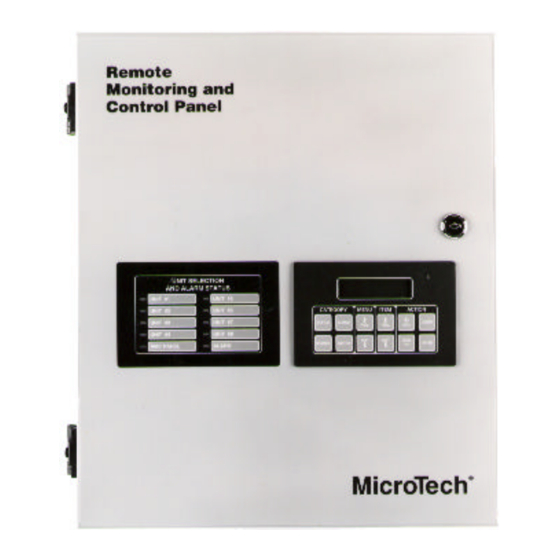
MicroTech ® Remote Monitoring and Control Panel
Applied Rooftop and Self-contained Air Conditioning Systems
For Use With McQuay Models RPS, RFS, RCS, RDT, RHS, RWS, RAH, SWP & SWT
© 1996 McQuay International
Operation Manual
OM-121
Group: Controls and
Network Systems
Part Number: 578998Y-01
Date: November, 1996
Advertisement
Table of Contents

Summary of Contents for McQuay MicroTech RMC-E01A
- Page 1 Network Systems Part Number: 578998Y-01 Date: November, 1996 MicroTech ® Remote Monitoring and Control Panel Applied Rooftop and Self-contained Air Conditioning Systems For Use With McQuay Models RPS, RFS, RCS, RDT, RHS, RWS, RAH, SWP & SWT © 1996 McQuay International...
-
Page 2: Table Of Contents
Contents Contents............................3 Figures............................4 Tables ............................. 4 Introduction ............................ 5 Software ID............................. 6 Software Compatibility........................ 6 GETTING STARTED ........................8 Using the Keypad/Display....................... 8 Menu Structure ........................... 9 Display Format.......................... 10 Password Protection ........................11 Keypad Functions........................11 Changing the Keypad-Controller Interface ................13 Keypad/Display Exercises ...................... -
Page 3: Figures
Table 19. Duct Static Pressure Parameters ..................38 Table 20. Change-and-Wait Controlled Variables and Set points for RMC Panel Control Strategies42 McQuay, MicroTech, and RoofPak are registered trademarks of McQuay International. Monitor and Open Protocol are trademarks of McQuay International. OM-121... -
Page 4: Introduction
Operation of this equipment in a residential area is likely to cause harmful interference in which case the user will be required to correct the interference at his or her own expense. McQuay International disclaims any liability resulting from any interference or for the correction thereof. -
Page 5: Software Id
Software ID MicroTech RMC controller software is factory installed and tested in each panel prior to shipment. The software is identified by a program code (also referred to as the “Ident”), which is printed on a small label affixed to the MCB. The program code is also encoded in the controller’s memory and is available for display on menu 16 of the keypad/display or a PC equipped with MicroTech Monitor™... -
Page 6: Table 3. Program Code Rmc-E01A Software Compatibility
Table 3. Program Code RMC-E01A Software Compatibility Unit Application Unit Type Compatible Programs Incompatible Programs VAV, using the RMC Panel’s common Applied 950164-040 950164 03 and earlier duct static pressure control feature Rooftop 950314-020 950314-01 950162-040 950162-03 and earlier 950313-020 950313-01 SCAC 950600-02C... -
Page 7: Getting Started
The MicroTech Remote Monitoring and Control (RMC) Panel is a self-contained device that is capable of monitoring and controlling up to eight McQuay applied rooftop or self-contained air conditioning (SCAC) units via network communications. You can display and modify information in the RMC Panel and its associated unit controllers with either of the following methods: •... -
Page 8: Menu Structure
Figure 1. Keypad/Display Board 1.RMC Status Schedule#1= Occ CATEGORY MENU ITEM ACTION STATUS ALARMS CLEAR PREV. PREV. INCR. NEXT NEXT DECR. CONTROL SWITCH ENTER Menu Structure The keypad accessible information in the MicroTech controller is organized in a menu structure to provide quick access. -
Page 9: Display Format
Figure 2. Keypad Accessible Menu Structure Category Menu Item Status Menu 1 Item 1 Item 2 Item 4 Menu 3 Item 1 Item 2 Item 4 Control Menu 4 Item 1 Item 2 Item 8 Menu 16 Item 1 Item 2 Item 14 Alarm Menu 17... -
Page 10: Password Protection
Figure 3. LCD Display Format Menu Line 10. Schedule #1 Item Line Sun 00:00-00:00 Field Password Protection The MicroTech controller includes password protection to guard against the entry of inadvertent changes. When you attempt to change the value of an adjustable parameter with the keypad, the controller prompts you to enter the password. - Page 11 menu 3), the Group #1 static pressure set point will be displayed (“Press Spt=” item under menu 5). is pressed again, the actual pressure will be displayed again. Note that the SWITCH SWITCH will not work with every menu item. Table 4. Status and Table 4 list the key destinations for SWITCH all applicable menu items.
-
Page 12: Changing The Keypad-Controller Interface
Changing the Keypad-Controller Interface The RMC Panel’s keypad/display can be directly interfaced with its own controller or remotely interfaced with any of its associated unit controllers via network communications. The controller that is currently selected is indicated by the Unit Selection LEDs on the panel face. When the RMC Panel’s keypad/display is interfaced to a unit controller, it acts identically to the unit’s keypad/display (see note below). - Page 13 8. Press in the Category key group. The actual duct pressure (“Group #1=” item under SWITCH menu 3, “Static Press”) is displayed. Now that the set point has been lowered, the pressure should drop. Clearing an Alarm In this exercise, assume that an alarm which requires a manual reset occurred in Unit #1. If the conditions that caused the alarm are gone, you can clear the alarm from the RMC Panel by using the following procedure.
-
Page 14: Keypad/Display Menu Reference
9. Since the stop minute field does not require editing, press again. The fourth field stops ENTER flashing, thus completing the edit. Note that the same result could have been accomplished by pressing the key instead of the key. CLEAR ENTER Keypad/Display Menu Reference The following tables show every menu, item, and field in the menu structure of the RMC controller. -
Page 15: Control Menus
Table 4. Status Menus Menu Item Name Name Range Key Destination WITCH Menu Item RMC Status Schedule #1=____ 10. Schedule #1 Unocc Schedule #2=____ 11. Schedule #2 Unocc Schedule #3=____ 12. Schedule #3 Unocc Schedule #4=____ 13. Schedule #4 Unocc Control Temp (Same as CT sensor) 5. -
Page 16: Operator's Guide
Group #4 Setup Menu 8, “Group #4,” contains parameters that are used to set up the fourth multiple-unit control group. Menu 8 is similar to menu 5; see “Group #1 Setup” above for more information. RMC Schedule Assignment Menu 9, “RMC Schedule,” allows you to assign one of the RMC Panel’s four schedules to each unit. It is not necessary to assign an RMC schedule to a unit;... -
Page 17: Table 5. Control Menus
Table 4. Control Menus Menu Item Name Name Field Range Key Destination WITCH (Default Shown) Menu Item Group Assign Unit #1 Group=1 – – 1 – 4 Unit #2 Group=1 – – 1 – 4 – – Unit #3 Group=NA 1 –... - Page 18 Menu Item Name Name Field Range Key Destination WITCH (Default Shown) Menu Item Group #4 Cntl Temp=Return Return 2. Control Temp Group #4= Space Temp Calc=Min 2. Control Temp Group #4= Press Calc=Min 3. Static Press Group #4= Press Spt=1.50"WC 0.20 –...
- Page 19 Menu Item Name Name Field Range Key Destination WITCH (Default Shown) Menu Item 0 – 59 0 – 23 0 – 59 Mon00:00–00:00 (Same as Sunday) 1. RMC Status Schedule #4= Tue00:00–00:00 (Same as Sunday) 1. RMC Status Schedule #4= Wed00:00–00:00 (Same as Sunday) 1.
-
Page 20: Alarm Menus
Menu Item Name Name Field Range Key Destination WITCH (Default Shown) Menu Item Time / Date Time=hr:mn:sc 0 – 23 – – 0 – 59 0 – 59 Sun – Sat – – daymm/dd/yy 1 – 12 1 – 31 0 –...
Need help?
Do you have a question about the MicroTech RMC-E01A and is the answer not in the manual?
Questions and answers