
Summary of Contents for Lynn Electronics CTR2-Mini+
- Page 1 CTR2-Mini+ Assembly Manual Version 1.1 November 18, 2022 CTR2-Mini+ Assembly Manual Version 1.1 Page 1...
-
Page 2: Table Of Contents
Contents Introduction ..............................3 Tools You Will Need ............................4 Bill Of Material (BOM) ........................... 4 PCB Kit ................................5 Pre-Cut Enclosure ............................5 Cutting your Own Enclosure ......................... 6 Drill Mounting Holes ..........................6 Interconnect Ribbon Cable ........................... 8 Installing the Components .......................... -
Page 3: Introduction
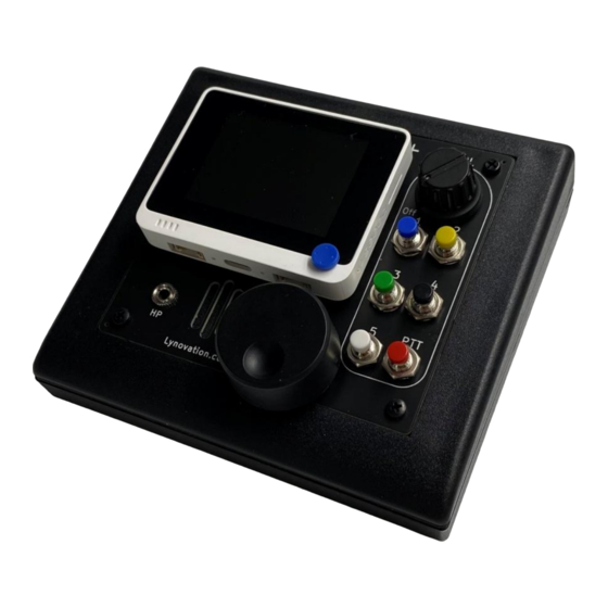
Introduction CTR2-Mini+ is an expanded version of CTR2-Mini. Like CTR2-Mini, the CTR2-Mini+ is a small radio controller based on the Wio Terminal from Seeed Studios. The Wio contains the processor, a 2.4” color LCD display, three user buttons, a 5-way switch, a micro-SD slot, and a 40-pin GPIO bus. The GPIO bus is compatible with many Raspberry Pi accessories. -
Page 4: Tools You Will Need
As we’ll see in this manual, the Mini+ only requires two circuit boards (and a back panel board) so it is easier to build and slightly less expensive to construct if you are controlling a single radio. The Mini+ is available as a bare PCB kit (with SMT components installed and mounting hardware included). -
Page 5: Pcb Kit
PCB Kit The Mini+ PCB Kit consists of two PCBs, a back panel, and mounting hardware. All the SMT components are preinstalled at the PCB factory. You only need to install the through-hole components and build a ribbon cable. The front panel, shown on the left in the photo below, mounts flushes in the recess in the KEU-5 enclosure. -
Page 6: Cutting Your Own Enclosure
Cutting your Own Enclosure If you choose to purchase the KEU-5 enclosure from the Mouser BOM you’ll need to prepare it for mounting the circuit boards. Drill Mounting Holes The first task is to drill the mounting holes in the bottom and top sections of the KEU-5 enclosure. - Page 7 Next, print out the template in Appendix B and cut it out. Lay it in the recess in the top panel and mark the cut lines as shown the left photo below. Use a fine-tooth coping saw or a Dremel tool to grub out the inside of the recess.
-
Page 8: Interconnect Ribbon Cable
Interconnect Ribbon Cable A 60mm 16-conductor ribbon cable connects the front panel PCB to the base PCB. To build this cable, cut an 80mm length of 16-conductor ribbon cable then install the ribbon cable connectors on each end as shown below. The finish length after the strain-reliefs are installed should be around 60mm. You can build this cable longer if you want more space between the board when you assemble or disassemble the enclosure but I find 60mm to be about right. -
Page 9: Installing The Components
Installing the Components I find it’s much easier to install components if the board is installed in a PCB vise. Working with the bottom of the board facing up I insert each connector into its holes from under the board. I hold the solder with my left thumb and index finger and use my left middle finger to hold the connector in position. -
Page 10: 16-Pin Ribbon Connector - J3
16-Pin Ribbon Connector – J3 Let’s start by installing J3, the 16-pin ribbon cable connector. As shown in the photo below this connector mounts on the top of the PCB and the pins face backwards toward the connectors on the rear of the board. -
Page 11: Dual-Row 8-Pin Header
Once you’re done the board should look like the photo below. You’ll want to use some flux remover to clean off the flux. Jacks installed Dual-Row 8-Pin Header The final task of populating the base PCB is to install the dual- row 8-pin header for the internal radio I/O circuit. -
Page 12: Isolated Ptt And Key Output Relays
Isolated PTT and Key Output Relays If your radio is older and uses keying voltage greater than +50 volts, or uses negative voltage for grid- block keying you will need to install the PTT/Key Relay modification. This modification adds two reed relays to the Mini+ that allows you to key radios using voltages up to +/- 200 volts. -
Page 13: 16-Pin Ribbon Connector - J1
16-Pin Ribbon Connector – J1 The first connector you should install is J1, the 16- pin header connector. It mounts on the bottom of the board as shown here. Solder it from the top side of the board. J1 installed next to IC1 Once completed, trim the leads protruding on top with flush-cutters so the... -
Page 14: Headphone Jack, J4
Add a solder blob to each pad before installing components Headphone Jack, J4 Mount the headphone jack next. Add a slight bend to the center terminal on the barrel end to bring it down to the board before tightening it down. - Page 15 Next, take a short length of wire and put a 1/16” bend on one end to form a hook. This end will be set into the solder blob. Insert this wire through the top-center terminal and melt the hook into the solder blob on the right hand pad as shown in the photo on the right.
-
Page 16: Volume Control
Volume Control The volume control is a little harder to connect because it just has small pins without holes. Start by mounting the control to the bottom of the board. The anti-twist tab should drop into the small hole drilled partially through the PCB. -
Page 17: Encoder
Encoder Mount the encoder so the pins align with the pads on the board and tighten its mounting nut. There is no anti-rotation tab on the encoder (since it has no stops). Solder the two ground lugs to the board. Use a hook wire to solder the top lug to the pad as shown in photo to the right. -
Page 18: Pushbuttons
Pushbuttons Install the pushbuttons last. Mount them to the bottom of the PCB. I put the washers on top, under the nut so I don’t scratch the panel when tightening the nuts. I like colored buttons but you can use any color you want. -
Page 19: Speaker
Speaker The speaker should be installed after you have installed all the other components and cleaned the rosin off the board. The solvent will melt the foam and glue that attaches the speaker to the board. To install the speaker remove the paper on the speaker’s face and stick the speaker down to the back of the PCB using the silkscreened oval as your guide. - Page 20 Connect the ribbon cable to J3 connector on the base board. Hold the top section over the bottom section and connect the other end of the ribbon cable to the J1 connector on the front panel. Secure the two enclosure halves using the provided screws and install the rubber feet (screws and feet are supplied with the enclosure).
-
Page 21: Quick Start Guide
Quick Start Guide Now that you have your Mini+ assembled you’re almost ready to start using it. There a just a couple of things that you need to do first... 1. Insert a micro SD card into the Wio Terminal. Any size from 128 MB to 16 GB will do. The card slot is just below the power switch on the left side. - Page 22 8. You will find it is easier to set up the Tx Message buffers, WiFi addresses, etc. if you connect your PC to the Wio’s USB-C port then open a terminal program to connect to the Mini+. Select the COM port created by the Wio Terminal and set the baud rate to 115200. Once connected, press the [Enter] key on your keyboard to start Terminal Mode.
-
Page 23: Appendix A - Schematics
Appendix A - Schematics Front Panel Schematic v1.2 CTR2-Mini+ Assembly Manual Version 1.1 Page 23... - Page 24 Base Schematic v1.1 CTR2-Mini+ Assembly Manual Version 1.1 Page 24...
-
Page 25: Appendix B - Top Section Grubbing Template
Appendix B – Top Section Grubbing Template The grubbing template for the top section of the KEU-5 enclosure is shown below full size. Print this page and cut the template out. Lay the template in the recess on the top section of the enclosure and use it to mark the cutout. -
Page 26: Appendix C - Radio Wiring Diagrams
Appendix C – Radio Wiring Diagrams This section contains the wiring diagrams you’ll need to connect the Radio I/O module to your radio. Many of them are simple mono or stereo 1/8” (3.5mm) to 1/8” cables. Others require a custom connector to be added to a factory built stereo to mono adapter such as a DB9, or a 6 or8-pin mini-DIN. - Page 27 CTR2-Mini+ Assembly Manual Version 1.1 Page 27...
- Page 28 CTR2-Mini+ Assembly Manual Version 1.1 Page 28...
Need help?
Do you have a question about the CTR2-Mini+ and is the answer not in the manual?
Questions and answers