
Summary of Contents for Norfield 1020
- Page 1 1020/1020K DOUBLE END TRIM SAW RODUCT AND PERATIONS ANUAL 17-245 DOCUMENT NUMBER Rev 6 Eff. S/N TS-1902 Release 0...
- Page 2 Norfield Industries is the name that represents Quality, Reliability, Support, Innovation and True Customer Service. We have been dedicated to providing quality products and excellent customer service for more than 40 years. Norfield Industries has earned a reputation in the pre-hanging industry for setting standards for reliable machinery, full technical support,...
-
Page 3: Table Of Contents
SPECIFICATIONS ............................ 10 INSTALLATION ............................11 1.1 SHIPPING DAMAGE AND SHORTAGES .................... 11 1.2 INSTALLATION ............................ 11 1.3 POSITIONING THE 1020 DOUBLE END TRIM SAW ................ 11 1.4 LEVELING ............................. 12 1.5 ELECTRICAL ............................12 1.6 AIR SUPPLY AND CONNECTION ....................... 13 1.7 REGULATOR SETTING AND TYPE OF OIL .................. - Page 4 3.1 ADJUSTING THE MACHINE BACK TO FACTORY SETTINGS ............26 3.2 REESTABLISHING THE CENTER-MARK SCRIBE LINE ..............29 3.3 ADJUSTING THE SHOCK ABSORBER ....................31 3.4 ADJUSTMENT OF THE FEED ASSEMBLY STOPS ................31 3.5 ADJUSTING THE CYCLE RATE OF THE KERFING MOTORS............32 3.6 ADJUSTING THE FEED ASSEMBLY CYCLES PER MINUTE ............
- Page 5 ..........................73 SCHEMATICS 1020 FLOOR LAYOUT ..........................77 APPENDIX C ............................. 78 BASIC PRINCIPLES OF PNEUMATIC PLUMBING ................78...
-
Page 6: Introduction
A safety system including guards, saw-motor brakes, and mechanical/electrical E-stop functions are designed to provide operator safety. Prior to shipment from our factory each Norfield machine is put through a series of tests and inspections to insure that you are provided with the highest quality product for your business. -
Page 7: Safety Information
STOP! Protect Yourself This manual contains information that is important to the safe operation of your Norfield equipment. LABEL AND DEFINITIONS Danger indicates an imminently hazardous situation, which if not avoided, WILL result in death or serious injury. Warning indicates a potentially hazardous situation which, if not avoided, COULD result in death or serious injury. - Page 8 Do not operate this machine unless all guards are in place and working correctly. If any guards or hazard labels are missing or damaged call Norfield's Service department immediately and request a replacement at 800-824-6242.
- Page 9 Woodworking machinery is inherently dangerous, common sense and good safety practices are your best defense against injury. If you have any questions regarding the correct operation of the machine and safety procedures in this manual call the Norfield Industries Service Department at 800-824-6242.
-
Page 10: Specifications
Approximate Weight: 1600 lbs. Space requirements: Width 9'6" x Length 18'0" Machine Capacity Rate: 30 Pieces Per Minute Machine Capabilities: 1020 & 1020K (CASING & BRICKMOLD) Length 1 '-6" To 8'-0" Width TO 3-1/2" Thickness 3/8" To 1-1/2" Undercut Angle... -
Page 11: Installation
1.2 INSTALLATION The information in this chapter refers to the installation and setup of the Norfield 1020 Double End Trim Saw. Since the purchase of the machine includes a startup by a Field... -
Page 12: Leveling
N S T A L L A T I O N 1.4 LEVELING It is important to level the machine across the two ends so that there is no twist or strain on the frame rails. This machine will not function properly if the frame is twisted. It is also desirable to level the machine from end to end. -
Page 13: Air Supply And Connection
1.8 DUST COLLECTOR (OPTIONAL) If the dust collection option was purchased with this Norfield 1020 Double End Trim Saw, or if you wish to connect this machine to an existing in-house dust collector, an 8 inch diameter hose is required. If the optional dust collector was purchased with this machine... -
Page 14: Basic Installation Adjustments
N S T A L L A T I O N 1.9 BASIC INSTALLATION ADJUSTMENTS Your new Norfield Industries machine has been carefully adjusted at the factory prior to shipment, however we recommend that you check the following initial perimeters to insure proper operation before running any material through the machine for the first time. - Page 15 N S T A L L A T I O N 1.9 BASIC INSTALLATION ADJUSTMENTS (CONT.) Next, check the position of the Crutch Tip. To do this, manually raise both Crutch Tips until they stop. Using the two Feed Assemblies manually push the material forward until the feed assembly comes into contact with the stop.
-
Page 16: Major Components And Controls
N S T A L L A T I O N 1.10 MAJOR COMPONENTS AND CONTROLS... -
Page 17: Operational Settings
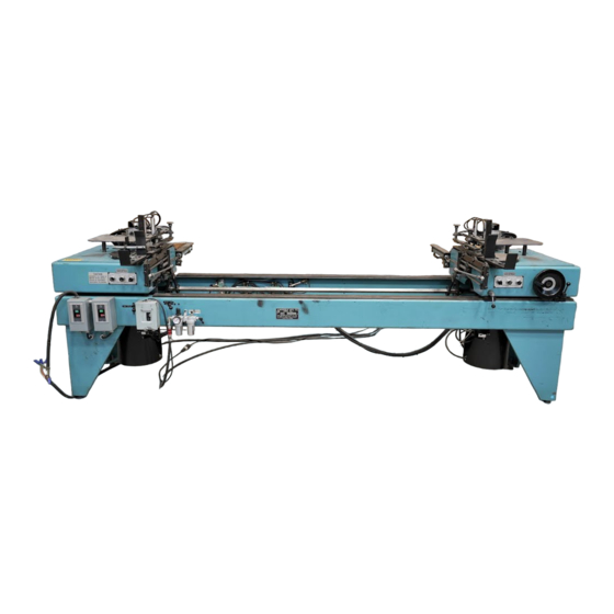
O P E R AT I O N A L S E T T I N G S 2.1 QUICK-START GUIDE The Norfield Industries 1020 DOUBLE END TRIM SAW consists of two saw canisters supported on a common frame. The left or stationary saw canister is fixed and the right saw canister is adjustable to allow setting for the desired length of cut. - Page 18 21. Once these checks have been made and you are satisfied with the specifications you are ready to begin using your new Norfield 1020 double end trim saw.
-
Page 19: Setting The Machine To Do Miter Cuts Or End Cuts
P E R A T I O N A L E T T I N G S 2.2 SETTING THE MACHINE TO DO MITTER CUTS OR END CUTS To adjust the saws to perform a 45-degree miter cut or a 90-degree end cut: 1. -
Page 20: Setting Up To Cut Different Width Materials
P E R A T I O N A L E T T I N G S 2.4 SETTING UP TO CUT DIFFERENT WIDTH MATERIALS If the thickness of the material does not change there are only two adjustments to make when setting the machine for different widths of materials, Please refer to the following: 1. -
Page 21: Resetting The Crutch Tips For Different Width Material
P E R A T I O N A L E T T I N G S 2.5 RESETTING THE CRUTCH TIPS FOR DIFFERENT WIDTH MATERIAL To adjust the Crutch Tips for different widths of material so that the material is held correctly while being cut refer to the following procedure: 1. -
Page 22: Setting Up To Cut Material Over 3" Wide
P E R A T I O N A L E T T I N G S 2.6 SETTING UP TO CUT MATERIAL OVER 3" WIDE If the material you wish to cut is over 3 inches wide, up to a maximum of 5-3/8 inches, it is necessary to reposition the Feed Assembly so that the material will feed into the machine correctly. -
Page 23: Setting Up For Different Thickness Material
P E R A T I O N A L E T T I N G S 2.6 SETTING UP TO CUT MATERIAL OVER 3" WIDE (CONT.) 9. With the nut loose adjust the shock absorber until it bottoms out against the Feed Drive Plate. -
Page 24: Setting The Undercut Angle Or Sill Bevel
5. On the Electrical Enclosure turn the desired Kerfing Power Switch to the on position. 6. Turn the Main Air Lever to the on position. 7. Depressing the Saw Start Button on the Electrical Enclosure will start the Kerfing motor. 8. Normal operation of the 1020 Double End Trim Saw may begin. -
Page 25: Resetting The Emergency Stop Switch
P E R A T I O N A L E T T I N G S 2.10 RESETTING THE EMERGENCY STOP SWITCH If depressed, the Emergency Stop will halt all operations. Both the pneumatic and electrical systems will be interrupted. Before resetting the Emergency Stop Switch the following steps must be taken. -
Page 26: Adjustments
At some point it may be desirable to completely re-set the 1020 Double End Trim Saw back to its factory setting. This section will also assist the user in synchronizing the Saw and Kerfing Assemblies to one another as well as synchronizing the Feed Assemblies. - Page 27 D J U S T M E N T S 3.1 ADJUSTING THE MACHINE BACK TO FACTORY SETTINGS (CONT.) 9. Locate the factory scribed center marks at the center of the Turntable. 1/2 inch past the center mark is a shorter scribed line. This is the factory setting on which the rear edge of the material to be cut should rest.
- Page 28 D J U S T M E N T S 3.1 ADJUSTING THE MACHINE BACK TO FACTORY SETTINGS (CONT.) 21. If the Kerfing option is installed steps 21 and 22 are required, if the Kerfing option is not installed skip to step 23. 22.
-
Page 29: Reestablishing The Center-Mark Scribe Line
D J U S T M E N T S 3.1 ADJUSTING THE MACHINE BACK TO FACTORY SETTINGS (CONT.) 35. Turn the main air on but do not start the saw cycle. Loosen the Head Lock Levers on the movable canister and change the cut length. The canister should move freely. If it does not move freely with the air on but will with the air off, repeat steps 28 through 33 until the Saw Canister will move freely with the air on. - Page 30 D J U S T M E N T S 3.2 REESTABLISHING THE CENTER-MARK SCRIBE LINE (CONT.) Measuring from the front edge of the turntable measure 6-1/4 inches parallel to the saw blade and scribe a line on the wear surface perpendicular to the insert. 8.
-
Page 31: Adjusting The Shock Absorber
D J U S T M E N T S 3.2 REESTABLISHING THE CENTER-MARK SCRIBE LINE (CONT.) 22. Replace the two guards that cover the Feed Assembly. 23. Replace the two Blade Guards. 24. This machine is now ready to resume normal operation. 3.3 ADJUSTING THE SHOCK ABSORBER To correctly adjust the position of the shock absorbers so that they are being depressed approximately ¾... -
Page 32: Adjusting The Cycle Rate Of The Kerfing Motors
D J U S T M E N T S 3.4 ADJUSTMENT OF THE FEED ASSEMBLY STOPS (CONT.) 8. Manually push the Feed Assembly forward until they stop. 9. On the Stationary Saw Canister Feed Assembly loosen the two 3/4 inch Clamp Collars and the Stop Clamp Block. -
Page 33: Adjusting The Feed Assembly Cycles Per Minute
D J U S T M E N T S 3.5 ADJUSTING THE CYCLE RATE OF THE KERFING MOTORS (CONT.) 10. Locate the two flow control valves at each end of the pneumatic cylinder on the Kerfing Assemblies. The flow control valve at the front of the cylinder controls the forward stroke rate of the assembly. - Page 34 D J U S T M E N T S 3.6 ADJUSTING THE FEED ASSEMBLY CYCLES PER MINUTE (CONT.) 3. By turning the knob until the groove aligns with 0 on both shock absorbers will cause the cycling of the Feed Assembly will increase. Turning the knob to a higher number will cause the Set Screw shock absorber to increase the damping effect and...
- Page 35 D J U S T M E N T S 3.6 ADJUSTING THE FEED ASSEMBLY CYCLES PER MINUTE (CONT.) 16. If necessary, close one or both of the valves located on the end of the Feed Assembly Cylinder so the two Feed Assemblies strike their respective shock absorbers simultaneously, usually no more than 1 additional turn will be required.
-
Page 36: Feed Start And Feed Return Pilot Valve Adjustment
D J U S T M E N T S 3.6 ADJUSTING THE FEED ASSEMBLY CYCLES PER MINUTE (CONT.) 37. Replace all the guards that were previously remove to make these adjustments. 38. This machine is now ready to begin normal operation. 3.7 FEED START AND FEED RETURN PILOT VALVE ADJUSTMENT The feed pilot valves are located just below the feed assembly on the stationary saw canister. -
Page 37: Adjusting Height Of Kerfing Blades (Optional Equipment)
D J U S T M E N T S 3.8 ADJUSTING HEIGHT OF KERFING BLADES (OPTIONAL EQUIPMENT) Each kerfing motor is housed in its original casting that includes their standard adjustment mechanism. Each division on the ring represents 1/64 of an inch height adjustment. 1. -
Page 38: Saw Drive Belt Adjustment
D J U S T M E N T S 3.10 SAW DRIVE BELT ADJUSTMENT The Following adjustments require that the Safety Guards be removed while the machine is in operation, all persons operating the machine or assisting in this adjustment must take extreme caution to avoid injury. The following procedure is provided to assist you in adjusting the Saw Drive Belts. -
Page 39: Feed Sync Assembly Equalization Adjustment
D J U S T M E N T S 3.11 FEED SYNC ASSEMBLY EQUALIZATION ADJUSTMENT If the Feed Drive Arms have more than a 1/4 of an inch of play in Feed Drive Arm Assemblies. It may be necessary to adjust them so that they equalized when cycling material. -
Page 40: Adjustment Of Miter Or Square Cuts
D J U S T M E N T S 3.12 ADJUSTMENT OF MITER OR SQUARE CUTS The Following adjustments require that the Safety Guards be removed while the machine is in operation, all persons operating the machine or assisting in this adjustment must take extreme caution to avoid injury. 1. - Page 41 D J U S T M E N T S 3.12 ADJUSTMENT OF MITER OR SQUARE CUTS (CONT.) 23. Remove the lockout/tagout devices 24. The machine is now ready to resume normal operation...
-
Page 42: Maintenance
3. Note: the Coalescing element in the filter can be removed and cleaned. Wash it in denatured alcohol or hot soapy water, then tap it out. Replacement elements are available from Norfield. 4. Inspect the machine for loose fasteners (nuts and bolts). Check the pneumatic system for... -
Page 43: Monthly Checks: (Every 100-200 Hours Of Operation)
7. A 1020 operating at just over twenty-two cycles per minute will complete 10,000 cycles in seven and one-half hours. Wear on valves and cylinders is going to occur. The valves used in the machine can be rebui1t by installing an inexpensive o-ring kit. -
Page 44: Changing The Saw Blades
A I N T E N A N C E 4.6 CHANGING THE SAW BLADES To change the saw blades in the 1020 Double End Trim Saw the following procedure must be followed: 1. Turn off the Disconnect Switch and Lock and Tag out. -
Page 45: Saw Drive Mandrel Replacement
A I N T E N A N C E 4.7 CHANGING THE KERFING BLADES (CONT.) 6. Using a 3/4 inch wrench to hold the shaft from moving, remove the nut on located on the end of the arbor with a 1/2 inch end wrench turning counter clock-wise. 7. -
Page 46: Saw Drive Cylinder Replacement
6. Remove the two saw return valves from the mounting plate. (Do not disconnect the hoses) 7. Remove the valve mounting plate. 8. Using a 1/2 inch open-end wrench to hold the cylinder shaft, loosen the alignment insert nut with a 1-1/4 inch extra thin open-end wrench (Norfield part number 13-382). -
Page 47: Saw Drive Belt Replacement
A I N T E N A N C E 4.9 SAW DRIVE CYLINDER REPLACEMENT (CONT.) Note: There is an aluminum pin holding the alignment insert into the motor mount plate. To avoid breaking this pin be sure to prevent the cylinder shaft from rotating while loosening the 1-1/4”... - Page 48 A I N T E N A N C E 4.10 SAW DRIVE BELT REPLACEMENT (CONT.) 5. Loosen the four mounting bolts that go through the jacking screws. 6. Remove the two bolts closest to the motor shaft. 7. Lift the shaft end of the motor to release the belt from the pulley. 8.
-
Page 49: Troubleshooting
R O U B L E S H O O T I N G S E C T I O N 5 T R O U B L E S H O O T I N G 5.1 TROUBLE CHECK LIST This machine is equipped with a sequencing air system that is designed to give superior performance throughout the life of the machine. - Page 50 R O U B L E S H O O T I N G Symptom Probable Cause Solution Possible physical obstructions. Check and remove obstructions. Open the flow control momentarily to Possible plugged flow control. see if the obstruction will pass, if not remove and clean.
- Page 51 R O U B L E S H O O T I N G Symptom Probable Cause Solution Aligning insert on moveable end Tighten aligning insert on cylinder has unscrewed from cylinder shaft. shaft. Feed return pilot valve Adjust pilot feed valve. adjusted improperly.
- Page 52 P P E N D I X P P E N D I X...
- Page 53 P P E N D I X...
- Page 54 P P E N D I X A...
- Page 55 P P E N D I X P P E N D I X...
- Page 56 P P E N D I X...
- Page 57 P P E N D I X...
- Page 58 P P E N D I X...
- Page 59 P P E N D I X...
- Page 60 P P E N D I X...
- Page 61 P P E N D I X...
- Page 62 P P E N D I X...
- Page 63 P P E N D I X...
- Page 64 P P E N D I X...
- Page 65 P P E N D I X...
- Page 66 P P E N D I X A...
- Page 67 P P E N D I X...
- Page 68 P P E N D I X...
- Page 69 P P E N D I X...
- Page 70 P P E N D I X...
- Page 72 P P E N D I X...
- Page 73 P P E N D I X SCHEMATICS ELECTRICAL...
- Page 74 P P E N D I X 1020 ELECTRICAL POWER DISTRIBUTION & CONTROLS ITEM PART # PART DESCRIPTION QTY/ASSY 11-938 ALLEN BRADLEY 194E-A63-1753 DISCONNECT SWITCH 3 POLE 11-935 ALLEN BRADLEY 194E-A63-1756 DISC SWTCH 6 POLE (KERFING OPTION) 11-865 ALLEN BRADLEY 194L-G2853 DCON SWITCH SHAFT EXTENSION...
- Page 75 P P E N D I X PNEUMATIC...
- Page 76 P P E N D I X Pneumatic Schematic Part List Item Norfield P/N Description 10-038 HUMPHREY 250A-3-10-20 VALVE 10-017 SMC AS-2000 FLOW CONTROL 10-604 SMC NAS 3200F-NO2-11S FLOW CONTROL 4 10-153 BIMBA 314-D CYLINDER 10-126 ARO 0415-1009-120 CYLINDER 10-291...
- Page 77 P P E N D I X 1020 FLOOR LAYOUT...
- Page 78 Ultimately, this will shorten the life of any air tool. As protection against such, the engineers at Norfield Industries have developed a pneumatic system and guidelines, which when followed, will significantly help lengthen the service life of all your air components.
- Page 79 BASIC PRINCIPLES OF PNEUMATIC PLUMBING (CONT.) that are to be connected to it. The tee in the header of each feeder should be installed so that the feeder comes off the top of header line (refer to fig. 1-1).The compressor should be placed away from cutting areas where there is an overabundance of sawdust to contaminate the air cleaner.
- Page 80 All parts manufactured by Norfield and found to be defective will be given appropriate credit. All parts not manufactured by Norfield are covered by their respective manufacturer's warranty and will be sent to the original manufacturer for credit. When, and if, credit is issued to Norfield, we will in turn issue credit to your account. Limited Warranty Norfield warrants any and all such parts manufactured by them against defects in material or workmanship for a period of one-year from date of purchase.