Table of Contents

Summary of Contents for Atim Cloud Wireless ACW/SF8-LVL
- Page 1 ATIM Cloud Wireless Ultrasonic distance measurement User Guide Concerned models: ACW/SF8-LVL ACW/LW8-LVL ATIM Radiocommunications www.atim.com Chemin des Guillets info@atim.com 38250 Villard de Lans +33 4 76 95 50 65 France...
-
Page 2: Table Of Contents
Table of contents THIS USER GUIDE IS APPLICABLE TO THE FOLLOWING REFERENCES ................... 4 DOCUMENT VERSION HISTORY ..............................4 DISCLAIMER ....................................5 TRADEMARKS AND COPYRIGHT ..............................5 DECLARATION OF COMPLIANCE ..............................6 ENVIRONMENTAL RECOMMENDATIONS ............................ 7 ................................7 XPLOSIVE ATMOSPHERE ................................... - Page 3 Alert frame ....................................30 DOWNLINK ....................................31 .) ..............31 ONFIGURATION OF THE FRAME PARAMETERS SENDING PERIOD NUMBER OF SAMPLES ........................31 ONFIGURATION OF THE DISTANCE OFFSET PARAMETER ..................................32 HRESHOLD SETUP ..........................32 ONFIGURING SENSOR DETECTION THRESHOLDS TECHNICAL SUPPORT ................................33 ATIM_ACW-LVL_UG_EN_V1.5...
-
Page 4: This User Guide Is Applicable To The Following References
This user guide is applicable to the following references Product version Product references (Visible on the label of the product) LoRaWAN ACW/LW8-LVL Sigfox ACW/SF8-LVL Document version history Software Version Date Description Author version 06/03/2020 Document creation V0.0.1 25/03/2020 Correction V0.0.1... -
Page 5: Disclaimer
Trademarks and copyright ATIM radiocommunications®, ACW ATIM Cloud Wireless® and ARM Advanced Radio Modem® are registered trademarks of ATIM SARL in France. The other trademarks mentioned in this document are the property of their respective owners. -
Page 6: Declaration Of Compliance
Declaration of compliance All ACW Atim Cloud Wireless® products comply with the regulatory requirements of the R&TTE Directive (1999/5/EC), article 3: 1 SAFETY (Article 3.1a of the 1999/5/EC Directive) NF EN60950-1 Ed. 2006/A1:2010/A11:2009/A12:2011 (health) EN62479: 2010 (power <20mW) or EN62311:2008 (power > 20mW) 2 Electromagnetic compatibility (Article 3.1b of the 1999/5/EC Directive) -
Page 7: Environmental Recommendations
Environmental recommendations a. Explosive atmosphere Except for the ACW-ATEX line specifically intended for this purpose, do not use ACW radio modems in the presence of flammable gases or fumes. Using the equipment in such an environment constitutes a safety hazard. b. -
Page 8: Technical Specifications
Technical specifications Product Dimensions 100 x 100 x 40 mm Antenna Internal -25°C to +70°C (Operating mode) Temperature -40°C to +70°C (Storage mode) Casing IP 54 Battery 1x packs Lithium batteries Weight 300 g Frequency 865 – 870 MHz Power 25 mW (14 dBm) Sigfox: 100 bits/s Rate... -
Page 9: Casing
Casing Footprint Mounting Holes Dimensions are given in millimeters. The sensor is supplied with a mounting gasket, which must be used under certain mounting conditions. ATIM_ACW-LVL_UG_FR_V1.5... -
Page 10: Product Identification
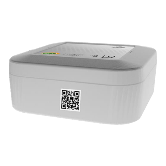
Product Identification The Sigfox or LoRaWAN IDs of the product are visible on the outside label on the side of the product, inside on the electronic card, and in the status section of the ACW configurator. For LoRaWAN modems, the communication keys are automatically given by the network (pairing by "Over The Air Activation", or OTAA). -
Page 11: Installation And Dismantling
Installation and dismantling It is necessary to open the box to the micro-USB port allowing the configuration of the module. To do this, you must unscrew the four screws which hold the top and bottom of the enclosure together. Screws to dismount the enclosure. - Page 12 IMPORTANT NOTE Avoid all kind of obstruction around the output of the sensor, especially in closed environments like a tank. A drilling of 60mm diameter is recommended. WARNING Take care about the size of the walls, the longer they are, the more interferences can happen. This can lead to false measurements or even prevent the sensors to work.
-
Page 13: Magnet Position
Be careful with the dimensions of the tank drilling: There is a constraint in the depth of drilling of the tank, if it is not respected, there is a risk of rebounds of the signal what can entrain errors of measurement. Z is the depth of the wall in mm &... -
Page 14: Operating
Operating Operating modes The operating of the ACW-LVL is divided between different modes: Operation mode: this is the default mode when starting the product. In this mode, the module periodically sends measurements according to the configuration applied (if the product has never been configured, the factory configuration applies, see Factory settings). -
Page 15: Product Start-Up
Product start-up In most cases, the ACW-LVL is started up before delivery (battery packs already connected) and then placed in deep standby to limit consumption. To place the product in its operating mode, bring a magnet close to the side of the case for 6 seconds. During these 6 seconds, the product LED should flash WHITE and then... -
Page 16: Test Frame Emission
Test frame emission When the product is in its operating mode (and only in this mode), it is possible to send a test frame (which avoids waiting for the next measurement frame) including a measurement sample. To do this, simply bring the magnet closer until the GREEN light signal goes out. -
Page 17: Acw Configurator
ACW configurator Compatible configurator version For an LVL with the following application software version: Use the version of ACW Configurator: Sigfox: V1.0.6 V5.3.1or later LoRaWAN: V1.0.6 Download and install the configuration software setup ’setupACW.exe‘ at: https://www.atim.com/en/products-configurator/ NOTE The ACW-LVL can be configured only from its configuration mode (otherwise the ACW configurator cannot detect it). To enter configuration mode, the device must enter its deep sleep mode first (magnet for 6 seconds), wait approximately 20 seconds for the entry to be effective and then wake up the device (magnet for 6 seconds again). -
Page 18: Acw-Lvl Setup
ACW-LVL setup Emission period and samples in the frame The transmission period corresponds to the time interval between each sending of a measurement frame. This period can be configured from 10 min to 255 h and its default value is 1 hour. In addition, it is possible to configure the number of samples in a frame . -
Page 19: Frame Timestamp
Frame timestamp It is possible to deactivate / activate the time stamping of all radio frames WARNING This option when activated monopolizes 4 bytes in the frame which cannot be used for useful data. Configuration of the Radio module The device can work in 3 different operating modes •... -
Page 20: Product Versions
o Local mode: The modulation of the frame’s switches to FSK. In this mode, you must choose the radio channel on which the product will transmit. To be able to receive the product frames, a radio modem with the same parameters is then required. This mode has no real concrete use case for the moment, but future developments of this mode will provide interesting point-to-point features. -
Page 21: Setup Validation
The gray slots on the graph correspond to the amplitude thresholds, defined by the range in width and amplitude threshold in height. Setup validation After having filled in all the configuration parameters, it is essential to click on the "Apply to ACW" button to send the configuration to the product It is also possible at any time to read the current configuration of the product which will update the parameters on the configurator or to reset the default configuration of the product. -
Page 22: Factory Settings
Factory settings Radio frames settings: Radio frame emission period: 10 minutes Number of samplings: 1 History depth: 1 General settings: Keep alive frame emission period: 4 days Timestamp: disabled Radio parameters: LoRaWAN Class A (for a LoRAWAN product) / Sigfox (For a Sigfox product) Sensor’s parameters: Level offset: 0 cm Threshold parameters... -
Page 23: Updates Of Acw
Updates of ACW When connected with Bluetooth Low Energy to the product, it is possible to update the different software that composes it. To do this, go to the menu Tools->Updater (CTRL+U) ATIM_ACW-LVL_UG_EN_V1.5... -
Page 24: Frames Format
Frames format Sigfox and LoRaWAN Uplink frame Byte 1 Byte 2 . . . Byte n Frame header Frame-specific data We can differentiate three types of frames: ⚫ Classic frame; New generation: Very close to the old frames, the difference is that you can activate the timestamp. -
Page 25: Measurement Frame
Different type of frames: Frame type Size of data Descriptions 0x00 Reserved 0x01 5 bytes Keep alive frame 0x02 0 byte Downlink request for network testing 0x03 8 bytes Reserved 0x04 Reserved 0x05 1 byte Test frame with counter 0x06 Variable (Cfg box) Response to a setup frame. -
Page 26: Alert Frame
For each channel, a header is inserted afterwards and is constituted as follows: Channel header Bit7 Bit6 Bit5 Bit4 Bit3 Bit2 Bit1 Bit0 Reserved = 0 Channel’s number Type of measurement In the case of ACW-LVL, the measurement type is 0x07 on 2 bytes for the distance in centimetres. In the case of the ACW-LVL, there is only 1 way (i.e. -
Page 27: Keep-Alive Frame
For each of the channels in alert a header is inserted and is constituted as follows: Channel Header Bit7 Bit6 Bit5 Bit4 Bit3 Bit2 Bit1 Bit0 Alert type Channel’s number Measurement type The type of alert field is used to identify whether it is a breach of the high threshold, the low threshold, or a return between the thresholds. -
Page 28: Error Frame
Error frame byte 1 - Header Bit7 Bit6 Bit5 Bit4 Bit3 Bit2 Bit1 Bit0 Timestamp Measurement Reserved Error frame generation frame = 0x0e If the Timestamp is activated, 4 bytes with the Timestamp value will be preceded by the header (byte 1). For each error message, a header is inserted and is formed as follows: Error frame header Bit7... - Page 29 0x93 ERR_KEEP_ALIVE_PERIOD Wrong keep alive frame structure 0x94 ERR_ENTER_DEEP_SLEEP The device entered deep sleep mode 0x95 ERR_BATTERY_LEVEL_LOW Low battery 0x96 ERR_ARM_TRANSMISSION A transmission has been initiated but an error has occurred 0x97 ERR_ARM_PAYLOAD_BIGGER Message size is too large for the capacity of the network 0x98 ERR_RADIO_PAIRING_TIMEOUT Impossibility to pair to a network within the fixed period...
-
Page 30: Examples Of Frames
Examples of frames Measurement frame Measurement frame without time stamp, no history and a sample number of 1. Byte 1 Byte 2 Byte 3 Byte 4 0xA0 0x07 0x0B 0x54 (new generation (channel 0, measurement measurement frame, type: distance) no history, 1 sample) In this frame the sensors returned the value 0x0B54 (290 centimetres) Measurement frame without time stamp, no history, and a sample number of 2. -
Page 31: Downlink
Downlink This functionality is available on ACW-LVL fulfilling the following conditions: Application software: Radio firmware: Sigfox version V1.0.6 V5932 LoRaWAN version V1.0.6 V5.1.1 The operation of the Downlink is explained in the document ATIM_ACW-DLConfig_UG, relating to version V1.2.0 of the ATIM Downlink Protocol (To obtain this document, please fill the contact form at this address: https://www.atim.com/en/technical-support/). -
Page 32: Threshold Setup
c. Threshold setup Parameter Frame size Index Byte 4 Byte 5 Byte 6 Byte 7 Byte 8 Byte 9 Byte 10 code (Byte 1) (Byte 2) (byte 3 0xD5 0x08 0x00 High threshold Low threshold hysteresis Duration For the threshold setup, the byte 0 is the header for an extended downlink frame + the number of the parameter (0xC0 | 0x15). -
Page 33: Technical Support
Technical support For any further information or technical question, you can open a ticket on our technical support dedicated webpage. ATIM_ACW-LVL_UG_EN_V1.5...
Need help?
Do you have a question about the ACW/SF8-LVL and is the answer not in the manual?
Questions and answers