
Summary of Contents for TICA TRV015 Series
- Page 1 Installation & Operation Manual Ventilator (Heat Recovery Fresh Air Handling Unit) Applicable to: TRV015 Series TRV025 Series TRV035 Series...
-
Page 2: Table Of Contents
Contents Product Overview ............................. 1 Features ............................1 Use Conditions ..........................2 Precautions/Safety ..........................2 Appearance Overview ........................3 Specifications ............................ 4 Controller ............................5 Installation ..............................8 Electrical Principle Diagram ........................13 Electrical principle diagram of basic version (ON/OFF type) ............13 Wiring diagram of the double control switch ................... -
Page 3: Product Overview
Product Overview Features 1. Fresh air function This product is provided with two AC high static pressure forward centrifugal fans. One brings fresh oxygen-enriched air to the room, and the other one discharges stale air from the room. 2. Air purification function This product adopts the high efficiency and low resistance filter of a world famous brand. -
Page 4: Use Conditions
TICA may improve and change the product without prior notice. TICA shall not be responsible for the damage accident that occurs because the equipment operates beyond the conditions defined in this manual. Do not use the product for other purposes such as cooling, drying, and heating. -
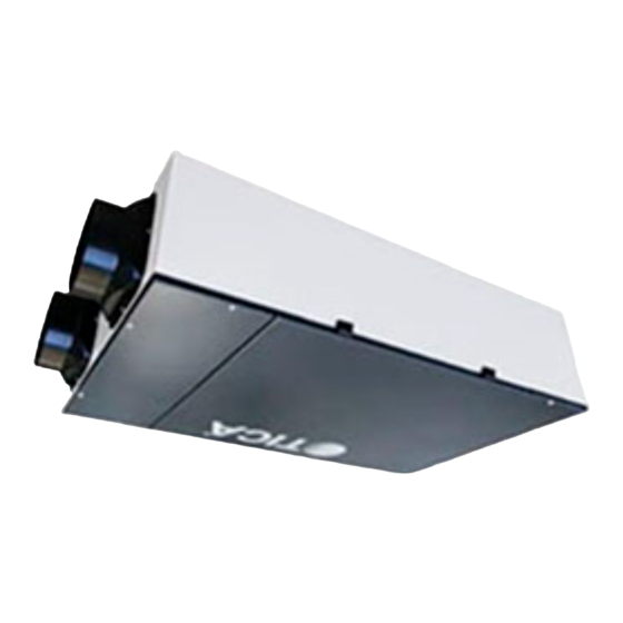
Page 5: Appearance Overview
For any exception or failure occurring during the operation, contact the technical service center. Do not try to operate or repair device by yourself. During normal operation, make sure that nobody can touch the live parts of the machine and the operating unit. -
Page 6: Specifications
Specifications Table 1 Specifications of ventilator (heat recovery fresh air handling unit) Ventilator (heat recovery fresh air handling unit) Model TRV015 TRV025 TRV035 Power supply 220V~50Hz 220V~50Hz 220V~50Hz Protection grade against Category I Category I Category I electric shock IP rating IPX2 IPX2 IPX2... -
Page 7: Controller
Controller Basic model - double control switch 1) Power-on/off OFF: Power off the unit ON: Power on the unit 2) Fan speed regulation LOW: The unit operates at the low speed HIGH: The unit operates at the high speed Upgraded version - LCD controller Power-on/off ... - Page 8 "1023" indicates the filter has worked for 1,023 hours. Hold down for more than 5s to reset the work duration of the filter. High configuration version - Intelligent controller 1) Power-on/off Press to start the unit. Press again to shut down the unit. 2) Fan speed regulation Press ▲...
- Page 9 change the value. Press again to switch to PM2.5 concentration setting. The position displaying the CO and PM2.5 concentration originally will display the set value and blink. Press ▲ and ▼ to change the value. If no keystroke operation is performed within 10s, the controller automatically saves the settings and returns to the normal operating state.
-
Page 10: Installation
Design and construction should be implemented according to the relevant codes and regulations of the state. Otherwise, the unit may fail to work normally. For the after-sales service of this unit, TICA will charge a fee.. Installation position (1) The following sites should be avoided for installation: ... - Page 11 Note: Note to prevent gases from flowing back to the room. Preparations before installation 1. Unpack the unit before installation, and check whether the unit appearance is in good condition and whether unit is not deformed. Check whether accessories are complete according to the packing list.
- Page 12 Installation 1. Follow instructions in this operation manual to install the product. Refer to the figure below. Return air pipeline Lifting bolt Fresh air pipe insulation material (return air) Pipe cover (supply air) Thermal insulation material for Air supply discharge duct Return air grille grille (outdoor fresh air)
- Page 13 3. Install the ducts. Use elbow as less as possible in the pipeline, and design the bending part of the elbow in an arc shape (90° right angle bending should be avoided). See Figure 5. (1) Excessive bending; (2) Multi-bending (3) Reduce the connecting pipe diameter Prohibited Prohibited...
- Page 14 and the return air inlet is far, or the air outlet is far and the return air inlet is near. The interval between the discharge air outlet and the fresh air outlet should be about 2 m, preventing stale indoor air from returning to the room. The minimum sizes of vents are provided below: Model Vent Size...
-
Page 15: Electrical Principle Diagram
Electrical Principle Diagram Electrical principle diagram of basic version (ON/OFF type) TRV015ACA/TRV025ACA ★ Note: The dashed lines indicate the wires to be connected on site. Low speed High speed Power supply 220V ~ 50Hz Blue Black Name Symbol Terminal block Black Blue Black... -
Page 16: Wiring Diagram Of The Double Control Switch
Wiring diagram of the double control switch Short the two points with a wire Connect to the terminal block High, high speed for the fan Connect to the live wire L of 220V power supply Connect to the terminal block Low, low speed for the fan Figure 9 Wiring diagram of the double control switch Electrical principle diagram of upgraded version (LCD controller) - Page 17 TRV035ACB ★ Note: The dashed lines indicate Controller the wires to be connected on site. Power supply 220V ~ 50Hz Blue Red Black Orange Blue Red Black Orange Symbol Name Terminal block Starting capacitor Fan control panel Yellow/green Yellow/green Fresh air fan White White Discharge fan...
-
Page 18: Electrical Principle Diagram Of High Configuration (Intelligent Controller)
Electrical principle diagram of high configuration (intelligent controller) TRV015ACC/TRV025ACC Controller ★ Note: Short-circuit the high-speed level and the medium-speed level. Power supply: 220 V ~ 50 Hz Blue ★ Note: The dashed lines indicate Black the wires to be connected on site. Name Symbol Blue... - Page 19 TRV035ACC ★ Note: The dashed lines indicate Controller the wires to be connected on site. Power supply 220V ~ 50Hz Orange Orange B lue B lack Symbol Name B lue B lack Terminal block Starting capacitor Fan control panel Yell ow/gree n Yell ow/gree n Fresh air fan White...
-
Page 20: Electrical Installation
Electrical Installation 1. Wire layout Install the wires according to the national standard; The power cord should be fixed reliably lest the connecting terminal would be stressed. Do not pull the power cord forcibly; The 1.5 mm wire harness is recommended for the power cord. - Page 21 Configure wires according to the requirements. Otherwise, the unit may fail and electric shock or fire may occur. Special Notice TICA will not bear any responsibility for the outcomes resulting from reconstructing the electric control system without prior permission.
-
Page 22: Operation And Maintenance
Operation and Maintenance Check the connection line after the installation work is completed, and make sure to perform trial operation. Check before trial operation 1. Pipeline system check Check whether the duct direction is correct, whether the equipment suspension is firm, and whether the hanging bracket is coated with antirust paint;... - Page 23 Observe the air inlet/outlet status of each indoor/outdoor air port. If the air flow and direction of the indoor air port can be adjusted, adjust it to a proper status. Carefully check whether there is any abnormal noise in the ventilation system, and observe whether the screws at the joints of all parts get loose and whether the sealing effect of sealing strip is good.
- Page 24 Removing and installing related parts falls into the scope of maintenance operations and must be completed by professionals. Cleaning and replacing the filter The ventilator (heat recovery fresh air handling unit) contains one air filter. It is recommended to check it every one to two months, or determine the replacement cycle independently according to the power-on time or the decrease degree of air flow.
- Page 25 HRV core Metal hook Access door Fixing screw Filter Figure 12 Core replacing/overhauling steps Notes: 1. Use a vacuum cleaner to suck dust and dirt from the surface; do not wash it with water; 2. Install the core, filter and access panel in the original positions in sequence, make sure that the HRV core is fixed on the unit reliably, and tighten the screws;...
- Page 26 J30186000000 HRV core TRV035 B5080088 Double control switch Table 3 List of TRV015ACB/TRV025ACB/TRV035ACA vulnerable parts Item No. Name Used Qty for Single Unit Remarks B5270086 LCD controller Note: Continued Table 2. Table 4 List of TRV015ACC/TRV025ACC/TRV035ACA vulnerable parts Item No. Name Used Qty for Single Unit Remarks...
-
Page 27: After-Sales Service
E-mail: tica@ticachina.com Zip code: 210046 Service hotline in China: 4008-601-601 Note: Due to constant improvement and innovation of TICA's products, the product models, specifications and parameters contained in this document are subject to change without prior notice. FORM NO.B21101G1 Version: 7...
Need help?
Do you have a question about the TRV015 Series and is the answer not in the manual?
Questions and answers