Table of Contents
Advertisement
Quick Links
SPECIFICATION *)
Model
Voltage
Frequency
Input
Ampere
Oil Charge
Refrigerant Charge ( NON-CFC)
Temperature Control
Defrosting System
Cooling System ( Evaporator )
Cooling Performance
o
( AT 32
C )
Blowing Agent
Thickness Insulation
Capacity (Liters)
Color
Cabinet Dimension
( External Dimension)
Net Weight **)
*) Specification subject to change without prior notice.
**) Weight and dimension are actual condition.
Manual Service
Dial Position
o
FC Room (
C )
o
PC Room (
C )
Wide
Depth
Height
Manufactured for Panasonic Corporation
Manufactured by PT Panasonic Manufacturing Indonesia, Jakarta
Made in Indonesia
NR - AF172SNAE
NR - AF172SNWG
NR - AF172SNAE
220 - 240 Volt ~
0.63 - 0.74 A
195 ± 5 ml ( Freol Alpha - 22 )
80 ± 5 gram ( HFC-134a )
Dial Adjustment
Manual Defrost Start - Manual Defrost Stop
Direct Cooling ( Roll Bond Evaporator )
Cold
-5.0 ± 2.5
6.0 ± 2.5
Polyurethane
160 Liter ( FC = 19 Liter )
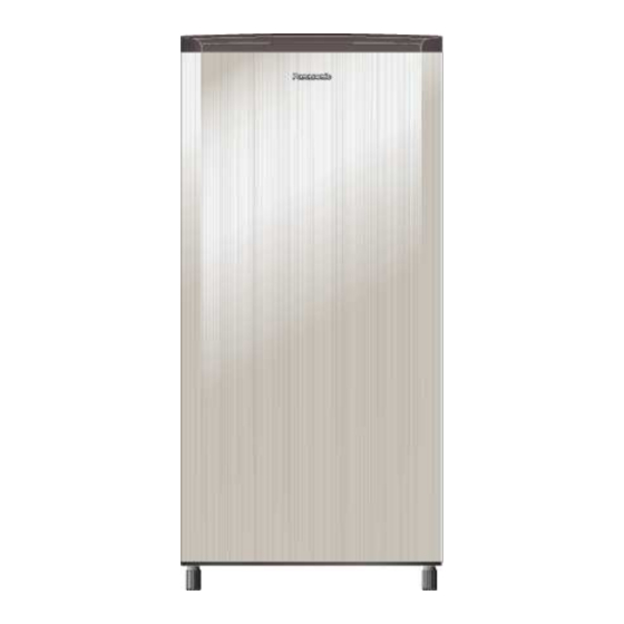
Champagne ( Starlight Silver )
-1-
Order No.: PMIRF1303026C3
Refrigerator
NR - AF172SNWG
50 Hz
85 W
Colder
-9.0 ± 2.5
3.0 ± 2.5
40 mm
525 mm
510 mm
1201 mm
27 Kg
Coldest
-16.0 ± 2.5
-3.0 ± 2.5
Advertisement
Table of Contents

Related Manuals for Panasonic NR-AF172SNAE


Summary of Contents for Panasonic NR-AF172SNAE
- Page 1 ( External Dimension) 1201 mm Height 27 Kg Net Weight **) *) Specification subject to change without prior notice. **) Weight and dimension are actual condition. Manufactured for Panasonic Corporation Manufactured by PT Panasonic Manufacturing Indonesia, Jakarta Made in Indonesia...
-
Page 2: Table Of Contents
Content: Items Page Safety Cautions for Repairing Part Identification III. Dimension Installation Schematic Diagram Wiring Diagram VII. Cooling Circulation and Main Component Function VIII. Repairing Devices Which are Exclusive - Use for HFC-134a Refrigerant Repairing Standard for Refrigerating Unit HFC-134a Tool for Repairing Refrigerating Unit HFC-134a Refrigerating Unit Repairing Procedure XII. -
Page 3: Safety Cautions For Repairing
I. Safety Cautions for Repairing When you repair refrigerator, please kindly take care of following cautions. a) Warning Before repairing unit, unplug service cord Before you repair refrigerator, unplug the service cord. ● Use authentic parts when repairing When you replace the parts, please use authentic parts to replace defective parts. ●... -
Page 4: Part Identification
II. PART IDENTIFICATION DOOR EVA. TRIM EVA ICE TRAY EGG TRAY 8 EGG SHELF CHILLED CASE UTILITY SHELF COVER LAMP TRAY PC BOX CONTROL (NR-AF172SNWG) SHELF NET PC (NR-AF172SNAE) BOTTLE SHELF COVER CRISPER CRISPER LEG SHELL ADJUSTER BOLT III. DIMENSION... -
Page 5: Installation
IV. INSTALLATION Placement, make sure that circulation of the Make sure that the refrigerator is placed on a air where the Refrigerator should be at least hard and level surface to prevent vibration 10 cm, both side 12 cm, and top 10 cm. and noise. -
Page 6: Wiring Diagram
VI. WIRING DIAGRAM NR-AF172SNWG NR-AF172SNAE VII. COOLING CIRCULATION AND MAIN COMPONENT FUNCTION FUNCTION OF EACH COMPONENT 1. COMPRESSOR The function is to compress refrigerant gaseous so that make the temperature and pressure high. 2. CONDENSOR The function is to lower down the refrigerant temperature, so it is liquified with same pressure. -
Page 7: Repairing Devices Which Are Exclusive - Use For Hfc-134A Refrigerant
VIII. REPAIRING DEVICES WHICH ARE EXCLUSIVE - USE FOR HFC-134a REFRIGERANT This refrigerator use Compressor with Ester Oil. Ester Oil employed as new compressor oil for refrigerant HFC-134a. Ester Oil is characteristic of higher hygroscopicity. When moisture leaks into the refrigerating unit, it will chemically react with the moisture and solid substance clogging the pipe will form. -
Page 8: Tool For Repairing Refrigerating Unit Hfc-134A
X. TOOL FOR REPAIRING REFRIGERATING UNIT HFC-134a Caution: Conventional repairing devices for CFC-12 can not connect with repairing devices for HFC- 134A. Because the shape of fitting for HFC-134A (M10 x P1.5 mm) is different from conventional ones. Be sure connect the adaptor with vacuum pump, so it that the vacuum pump can be used for both CFC-12 and HFC-134a. -
Page 9: Refrigerating Unit Repairing Procedure
XI. REFRIGERATING UNIT REPAIRING PROCEDURE STANDARD PROCEDURE IMPORTANT THINGS Diagnosing the trouble Refer to the TROUBLESHOOTING Discharging the refrigerant Removing the Compressor Checking the compressor oil A little discoloration Severe discoloration (light yellow) (light brown) * For purging the pipe, use HFC-134a as liquid state. Purging the pipe at * Never use HCFC-141b, HCFC-22 for purging. -
Page 10: Method To Repairing Refrigerating Unit 10
XII. METHOD TO REPAIRING REFRIGERATING UNIT CONDITION I. NOT COLD Compressor not run CHECK CAUSE SUSPECT ANALYSIS ACTION Both terminal direct Check with Ohm Compressor run Compressor run Change Thermostat joining Meter ( Tester ) Compressor not run OLP broken Check with M.Tester Change O L P Starting PTC broken... - Page 11 1. TROUBLE - SHOOTING Symptom: No cooling at all or insuficient cooling Check starting Replace faulty electric No good Does compressor run ? circuit parts (Thermostat, starting relay, motor protector, starting capacitor, running capacitor, defrost timer) Check Oil Compressor Check resistance of Compressor locking motor winding with ohm meter...
- Page 12 Check pressure at High Pressure side Install Pierching Plier with Pressure Gauge at Discharge near Compressor, then check pressure from compressor running. If Compressor stop, start compressor again about ± 5 minutes until stabile pressure, then check pressure Note: Before measuring, make sure the Pressure Gauge at " 0 " position. If not at " 0 " position, adjust the Screw at Pressure Gauge.
- Page 13 2. PREPARATION 1. Remove Cover Protector from Compressor Suction pipe Compressor 2. Replace Starting Relay. 3. Replace Over Load Protector (OLP). 3. DISCHARGING THE REFRIGERANT Cut the compreesor sharge pipe and capillary pipe near Dryer to discharge Refrigerant. 4. REMOVING THE COMPRESSOR Disconnect the discharge pipe from the Discharge Pipe compressor with brazing.
- Page 14 High pressure side Connect the process - tube - fitting with the inlet pipe of dryer by wrenches. Note: Do not purge the pipe at high - pressure side from compressor side so that no deteriorated oil can flow into the condenser. Connect the charge cylinder (for HFC-134a) with the process - tube - fitting.
- Page 15 7. ASSEMBLING THE COMPRESSOR AND THE DRYER General Clause > It should be finished within 30 minutes. When pipe purging no need From the process of removing compressor until the process of setting compressor and dryer (just before vacuum pumping process). When pipe purging has need From the time just after pipe cleaning is completed until the process of setting compressor and dryer (just before vacuum pumping process).
- Page 16 8. VACUUM PUMPING General Clause: a Vacuum pumping should be done more than 60 minutes from 2 portions. One portion at high - pressure side and one portion at low - pressure side. b Be sure the Adaptor good connect to vacuum pump. The Adaptor can stop oil flow from Vacuum Pump to Cooling Unit HFC-134a, after Manifold Gauge and Charge Hose vacuum condition.
- Page 17 9. MEMASUKKAN REFRIGERANT DARI CYLINDER KEDALAM CHARGE CYLINDER REFRIGERANT CHARGING FROM CYLINDER TO INSIDE OF CYLINDER CHARGE Preparation: Before vacuum pumping process, it should charging the refrigerant from Cylinder HFC- 134a to inside of Cylinder Charge. b Connect Cylinder Charge and Control Valve. Fix the Adaptor Charge at Cylinder HFC-134a.
- Page 18 5. Close quickly the valve as soon as the set amount is charged. Set the starting Relay and the overload protector. And run the compressor until pressure reading at the low pressure gauge shows 0 so that remaining refrigerant in the charge hose is taken in the refrigerating unit.
-
Page 19: Safety Check
XIII. SAFETY CHECK Make sure that the refrigerator repaired is secure and works properly. 1. INSULATION TEST Connect the Service Cord pin positive and negative except grounding Connect grounding Insulation test insulation tester to service cord of Refrigerator. Connect positif pin Insulation tester to body of Refrigerating Unit. -
Page 20: Instruction To Assembly Parts
XIV. INSTRUCTION TO ASSEMBLY PARTS INDICATED SAFETY PART -20-... -
Page 21: Part List 21
XV. PART LIST PART NUMBER PART NAME REMARK REVISION REVISION AF172SNAE AF172SNWG CURRENT CURRENT Jun-15 Jun-15 AE-138582 LEG SHELL 56 WASHER 5 x 12 x 0.8 MC 38-1915602-A For fix Leg Shell HEXAGON H 5 TS 20 MC 38-1757102-A For fix Leg Shell AF-188561 AF-134447 CROSSRAIL REAR... - Page 22 XV. PART LIST PART NUMBER PART NAME REMARK REVISION REVISION AF172SNAE AF172SNWG CURRENT CURRENT Jun-15 Jun-15 GROMMET COMPRESSOR AJ-165380 39-9411201 02-578321 PIN WIRE AJ-144430 AJ-144670 PLAIN WASHER WASHER HIPS (2 mm) SPCC 112095405 AF-192522 5 DRYER W COMPRESSOR GROUNDING BG-153420 38-4340900 38-430901 4 SPRING WASHER...
-
Page 23: Packing Instruction
XVI. PACKING INSTRUCTION Instruction Book AK-167882 AK-167881 AK-167880 Carton Box NR-AF172SNAE Carton Box NR-AF172SNWG AK-167970 Strapping Band SB15X07YL 326.130.080 AJ-108740 Top Cushion R/L AK-160660 Refrigerator Cover AJ-144630 AJ-165830 Front Layer Carton AK-153190 Pallet As. BK-129781 -23-...
Need help?
Do you have a question about the NR-AF172SNAE and is the answer not in the manual?
Questions and answers