Table of Contents
Advertisement
Quick Links
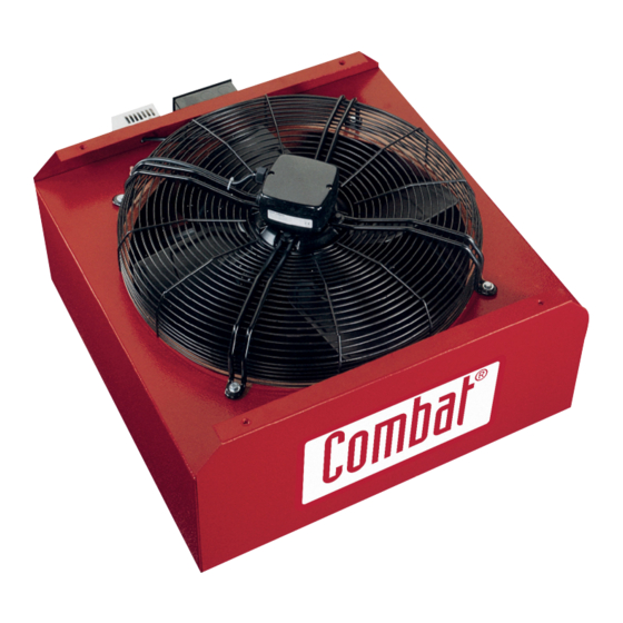
HVE Fans
TM
Energy Saving Fans
with control options
Installation, Operation and
Service Manual
HVE 400, HVE 450, HVE 650
WARNING
Improper installation, adjustment, alteration,
service or maintenance can result in death,
injury or property damage. Read the installation,
operation and service manual thoroughly
before installing or servicing this equipment.
Installation must be done by an electrician
qualified in the installation and service of
control systems for heating equipment.
Combat Heating Solutions Limited
Registered at
Unit 20 Red Mill Industrial Estate
Rigby Street
Wednesbury
West Midlands
WS10 0NP
Company Registration Number 11091275
Installer
Please take the time to read and understand
these instructions prior to any installation.
Installer must give a copy of this manual to the
owner.
Owner
Keep this manual in a safe place in order to provide
your service technician with necessary information
Tel:
Email:
Web:
Combat HVE Fans - Publication CBT0004 April 2019
0121 506 7700
uksales@combat.co.uk
www.combat.co.uk
1
Advertisement
Table of Contents

Summary of Contents for COMBAT HVE 400
- Page 1 Combat Heating Solutions Limited Registered at Unit 20 Red Mill Industrial Estate Rigby Street Wednesbury West Midlands Tel: 0121 506 7700 WS10 0NP Email: uksales@combat.co.uk Company Registration Number 11091275 Web: www.combat.co.uk Combat HVE Fans - Publication CBT0004 April 2019...
-
Page 2: Table Of Contents
- without the written permission of Combat Heating Solutions Limited Product Approval Combat appliances have been tested and CE certified as complying with the essential requirements of the Gas Appliance Directive, the Low Voltage Directive, the Electromagnetic Compatibility Directive and the Machinery Directive for use on natural gas and LPG when installed, commissioned and maintained in accordance with these instructions. -
Page 3: Section 1: Introduction
If you require additional manuals, contact Combat Heating Solutions Limited: Each HVE fan has a built in thermostat that allows it Tel +44 (0) 121 506 7700 or at www.combat.co.uk. to turn on when the ambient temperature at the fan exceeds the thermostat’s setpoint. -
Page 4: Safety Labels And Their Placement
FIGURE 1: Label Placement Description Part Number Logo Label 91040030 Shock Hazard Label 91008001 Address Label 91040006 Wiring Diagram Label 91040400 Terminal Connection Label (not shown) 91040401 Rating Plate Label 91010450 Combat Limited HVE Energy Saving Fans, Installation, Operation and Service Manual... -
Page 5: Section 2: Specifications
Section 2 Specifications 2.1 Electrical Specifications Supply: 230V, 50 Hz, 1 Ø, 20 A 2.2 Fan Specifications Model HVE 400 HVE 450 HVE 650 [m3/h] 3,600 6,300 10,800 Air Capacity [ft3/min] 2,120 3,710 6,360 Fan Diameter [mm] Motor Speed [RPM]... -
Page 6: Section 3: Critical Considerations
3.2 Minimum Required Installation Clearances Clearances around fan must be as indicated on Page 5, Section 2.3 to ensure access for servicing and correct operation. FIGURE 3: Suspension Methods Combat Limited HVE Energy Saving Fans, Installation, Operation and Service Manual... -
Page 7: Section 4: Installation
• Must be installed in a manner which alllows access to all serviceable components. Installation of the COMBAT HVE fan and the associated external electrical wiring must be completed by an 4.1.2 Suspension Mounting electrician qualified in the installation of control systems for heating equipment. -
Page 8: Section 5: Typical External Wiring Diagrams
FIGURE 8: Internal components Diagram Wiring Diagram Model/Part Numbers Model Description Part Number HVE400 Axial Fan 400mm 90750008 HVE450 Axial Fan 445mm 90750004 HVE650 Axial Fan 650mm A269 Thermostat 230V C2334B Combat Limited HVE Energy Saving Fans, Installation, Operation and Service Manual... -
Page 9: Section 6: Troubleshooting
Section 6 Troubleshooting 6.1 Sequence of Operation DANGER The WAC6 Fan Control offers manual control over HVE fan speeds. See Page 8, Section 5 wiring diagrams to utilize the HVE Fan thermostat. In this case, each fan will turn on when the temperature at the fan exceeds the thermostat set point. -
Page 10: Section 7: Replacement Parts
Electrical Shock Hazard Explosion Hazard Fire Hazard Carbon Monoxide Hazard Use only genuine COMBAt replacement parts per this installation, operation and service manual. Failure to follow these instructions can result in death, electric shock, injury or property damage DANGER Electrical Shock Hazard Disconnect electrics before service Equipment must be properly grounded. -
Page 11: Section 8: Service History
Section 8 Service History SERVICE 01 DATE: SERVICE 02 DATE: Engineer Name Engineer Name Company Name Company Name Telephone No. Telephone No. GasSafe Number GasSafe Number Comments Comments Signature Signature SERVICE 03 DATE: SERVICE 04 DATE: Engineer Name Engineer Name Company Name Company Name Telephone No. - Page 12 This product is not for residential use. ©2018 Combat Heating Solutions Limited. All rights reserved. No part of this work covered by the copyrights herein may be reproduced or copied in any form or by any means-graphic, electronic or mechanical, including photocopying, recording, taping or information storage and retrieval systems- without written permission of COMBAT Heating Solutions Limited.

Need help?
Do you have a question about the HVE 400 and is the answer not in the manual?
Questions and answers