Table of Contents

Subscribe to Our Youtube Channel
Related Manuals for Leutert 50


Summary of Contents for Leutert 50
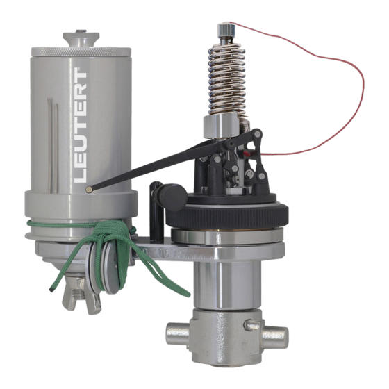
- Page 1 Engine Indicator Type 50 Type 30 Operating Instructions Engine Indicator The mechanical engine indicators type 50 and type 30 measure dynamic pressures. They are especially designed to analyze large two and four stroke Diesel engines.
- Page 2 Engine Indicators Type 50 and Type 30 - Operating Instructions Introduction This operating manual provides instructions on how to use this product correctly, effectively and safely for the intended purpose. Please read all instructions, notes on danger and warning attentively.
-
Page 3: Table Of Contents
Engine Indicators Type 50 and Type 30 - Operating Instructions Contents The Engine Indicator ............... 4 General Description ............4 1.2 Technical Specifications of the Indicators ......5 1.2.1 Indicator Type 50 ..........5 1.2.2 Indicator Type 30 ..........5 Assembly Drawing and Inventory .......... -
Page 4: The Engine Indicator
1/10. The upper part consists of the recording mechanism, the piston rod and the ring nut. The recording pencil of the indicator type 50 is interchangeable. To be able to measure higher pressure, the LEUTERT Indicators can be equipped with a smaller piston size. Corresponding to smaller piston size, higher pressure ranges can be indicated with the same spring. -
Page 5: Technical Specifications Of The Indicators
Engine Indicators Type 50 and Type 30 - Operating Instructions Technical Specifications of the Indicators 1.2.1 Indicator Type 50 This indicator is especially designed to analyze large two stroke Diesel engines. Max. Pressure : 300 bar Measuring range : see spring table... -
Page 6: Assembly Drawing And Inventory
Engine Indicators Type 50 and Type 30 - Operating Instructions Assembly Drawing and Inventory Part-No. Item Description Type 50 Piston 1/10 Type 50 Piston 1/5 Type 30 Piston 1/5 Indicator complete with 4656.00.00000 4663.00.00000 4611.00.00000 accessories, without spring & measuring scale Discontinued product. -
Page 7: The Indicator
Engine Indicators Type 50 and Type 30 - Operating Instructions The Indicator Part-No. Item Description Type 50 Piston 1/10 Type 50 Piston 1/5 Type 30 Piston 1/5 Indicator 4656.11.00000 4663.11.00000 4611.11.00000 Slotted nut 4651.11.03002 4651.11.03002 4611.11.03002 Stop screw 4651.11.03003 4651.11.03003 N.A. -
Page 8: The Bottom Part, Complete
Engine Indicators Type 50 and Type 30 - Operating Instructions 2.1.1 The Bottom Part, complete Part-No. Item Description Type 50 Piston 1/10 Type 50 Piston 1/5 Type 30 Piston 1/5 Bottom part, complete 4651.11.03100 4651.11.03200 4611.11.03100 Straight pin ZSTIFTD02.25600 ZSTIFTD02.25600 ZSTIFTD02.25600... -
Page 9: The Recording Mechanism
Engine Indicators Type 50 and Type 30 - Operating Instructions 2.1.3 The Recording Mechanism Part-No. Item Description Type 50 Piston 1/10 Type 50 Piston 1/5 Type 30 Piston 1/5 Recording mechanism 4651.11.11000 4651.11.11000 4611.11.12000 Turning ring 4651.11.11001 4651.11.11001 4611.11.12001 Support arm N.A. -
Page 10: The Drum, Complete
Engine Indicators Type 50 and Type 30 - Operating Instructions 2.1.4 The Drum, complete Part-No. Item Description Type 50 Piston 1/10 Type 50 Piston 1/5 Type 30 Piston 1/5 Drum, complete 4661.11.01000 4661.11.01000 4611.11.01000 Drum knob 4651.11.01001 4651.11.01001 4651.11.01001 Drum axle 4651.11.01002... -
Page 11: Tools And Accessories
Engine Indicators Type 50 and Type 30 - Operating Instructions Tools and Accessories Part-No. Item Description Type 50 Piston 1/10 Type 50 Piston 1/5 Type 30 Piston 1/5 Accessories box 4651.98.03100 4651.98.03100 4611.98.01100 Stand for instrument 4631.98.01001 4631.98.01001 4631.98.01001 Cord tightening hook 4651.98.00001... -
Page 12: The Indicator Spring
Engine Indicators Type 50 and Type 30 - Operating Instructions The Indicator Spring Indicator Type 50 Piston Piston Ø Scale Max. Pressure Spring-No. Part-No. 1/10 6.41 mm 0.35 mm/bar 140 bar 50 / 14 bar 4651.71.14000 1/10 6.41 mm 0.30 mm/bar... -
Page 13: Operating Procedure
Engine Indicators Type 50 and Type 30 - Operating Instructions Operating Procedure Remove the upper part from the bottom part by turning the ring nut. Lubricate the operative surfaces of the bottom part, piston rod and piston rod guide with top-quality, non-viscous cylinder oil. - Page 14 Engine Indicators Type 50 and Type 30 - Operating Instructions Blow through the connection line before mounting the indicator to prevent wrong indication of the engine pressure by any condensed water, oil or soot deposits in the connection line. DANGER: The valve ejects hot gas under high pressure. Danger of sparks and burning! Close the indicator valve.
-
Page 15: Changing The Spring
Engine Indicators Type 50 and Type 30 - Operating Instructions After verification of the indicator diagram it is very important to note all necessary data on the diagram, such as piston size of the indicator, spring number, engine number etc. - Page 16 Engine Indicators Type 50 and Type 30 - Operating Instructions Digital Pressure Indicator DPI The Digital Pressure Indicator DPI can be seen as the electronic equivalent of our range of mechanical indicators with all advantages of an electronic device and a very convincing price-performance ratio.
Need help?
Do you have a question about the 50 and is the answer not in the manual?
Questions and answers