Table of Contents
Advertisement
Quick Links
INSTALLATION AND OPERATING MANUAL
Translation of the original manual
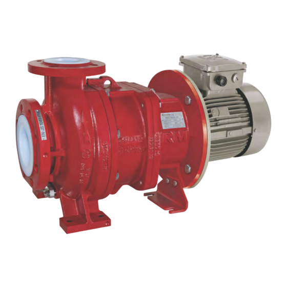
Series RMI-B
Sealless Chemical Magnetic
Drive Pump
Close-coupled design
Keep for future use!
This operating manual must be strictly observed before
transport, installation, operation and maintenance
Subject to change without notice.
Reproduction is generally permitted with indication of the source.
© Richter Chemie-Technik GmbH.
9430-055-en Revision 00 Edition 03/2018
Advertisement
Table of Contents

Summary of Contents for V&A RICHTER RMI-B Series
- Page 1 INSTALLATION AND OPERATING MANUAL Translation of the original manual Series RMI-B Sealless Chemical Magnetic Drive Pump Close-coupled design Keep for future use! This operating manual must be strictly observed before transport, installation, operation and maintenance Subject to change without notice. Reproduction is generally permitted with indication of the source.
-
Page 2: Table Of Contents
Series RMI-B Page close-coupled design List of Contents List of Contents ..........2 6 Commissioning / Shutdown ....14 Relevant documents ........3 6.1 Initial commissioning ......... 14 6.1.1 Filling the pump housing ....... 14 1 Technical data ........... 3 6.1.2 Start-up ............ -
Page 3: Relevant Documents
Series RMI-B Page close-coupled design Relevant documents ♦ Data sheet Appendix to the operating manual: ♦ Operational limits 9430-00-3030 ♦ Works certificate ♦ Declaration of conformity with ATEX ♦ Sectional drawing ♦ Declaration of conformity without ATEX RMI-B close-coupled design 9430-00-3002 ♦... -
Page 4: Tightening Torques
Series RMI-B Page close-coupled design Tightening torques Dry-running: Screws greased, tighten in diametrically opposite se- quence Housing screws 901/3 Size No. x size Tightening torque PN 16 PN20 [mm] [DIN/ISO] [Nm] 40-25-125 8 x M12 50-32-125 8 x M12 40-25-160 8 x M12 ATEX marking: 50-32-160... -
Page 5: Safety
Series RMI-B Page close-coupled design Safety This operating manual contains fundamental ♦ Risks to the environment through leaks of hazard- information which is to be observed during installation, ous substances. operation and maintenance. If the unit is used in potentially explosive must read before... -
Page 6: Notes On Safety For The Customer / Operator
Series RMI-B Page close-coupled design Furthermore, reference is made in this connection to Notes on safety for mainte- the Directive 95/C332/06 (ATEX 118a) which contains nance minimum regulations improving occupational health and safety of the workers who ♦ Strictly, work on the pump/unit may only be per- may be at risk from an explosive atmosphere. -
Page 7: Filling The Unit
Series RMI-B Page close-coupled design 2.6.1 Filling the unit 2.6.4 Identification During pump operation the wetted interior of The ex identification on the pump relates to the pump must always be filled with the liquid the pump section. A separate declaration of medium. -
Page 8: Temperature Limits
Series RMI-B Page close-coupled design Dry-running cannot only occur with an insuf- Table 2 ficiently filled interior but also in the event of Temperature class Limit value of the tem- high gas contents in the liquid medium. acc. to EN 13463-1 perature of the liquid Operation of the pump outside the admissible operating range may also lead to dry-running (e.g. -
Page 9: Transport, Storage And Disposal
Series RMI-B Page close-coupled design Transport, storage and disposal The pump or the unit must be transported Protect elastomers against UV light. properly. It must be ensured that during Generally, a storage period of 10 years do not transport the pump/unit remains in the hori- exceeded. -
Page 10: Product Description
Series RMI-B Page close-coupled design Product description The housing dimensions, nominal ratings and tech- The static tightness of the pump is guaranteed by nical requirements of the pump series RMI-B corre- the screw fittings of the bracket 344 and housing spond to ISO 2858 / DIN EN 22858 / DIN EN ISO 100. -
Page 11: Installation
Series RMI-B Page close-coupled design Installation Safety regulations Use flange gaskets suitable for the medium. The screw tightening torques in Section 1.1 are to Equipment which is operated in potentially be observed for tightening the flange screws. explosive areas must satisfy the explosion 5.4.1 Nominal size protection regulations. -
Page 12: Nozzle Loads
Series RMI-B Page close-coupled design 5.4.2 Nozzle loads 5.4.6 Venting and evacuating The pump can be subjected to nozzle loads acc. to Venting can take place into the discharge line or DIN EN ISO 5199. See also TIS 0541-02-0006. upstream of the discharge valve. A venting line can also be used as a bypass, drain or Changes in the length of the piping caused by flushing line. -
Page 13: Monitoring Facilities
Series RMI-B Page close-coupled design Monitoring facilities Electric connection Appropriate monitoring facilities are to be The operator is obligated to connect the assembly in recommended, depending on the require- accordance with existing regulations (IEC, VDE, ments placed on operational safety and etc.). -
Page 14: Commissioning / Shutdown
Series RMI-B Page close-coupled design Commissioning / Shutdown Initial commissioning The pump must not run dry during the check of the direction of rotation. Normally, the pumps have already been test-run with water. The pump must be completely filled with liquid. Unless special agreements have been reached, there The maximum admissible flow rate must not be ex- may still be some residual amounts of water in the... -
Page 15: Shutdown
Series RMI-B Page close-coupled design Shutdown Pump is started up without medium : ♦ The plain bearings in the pump may be de- ♦ Close discharge valve down to the position "mini- stroyed. mum flow rate" ♦ Other pump components may be destroyed due ♦... -
Page 16: Maintenance
Series RMI-B Page close-coupled design Maintenance Safety related screw connec- 7.5.1 Protective clothing tions Even if the pump has been properly evac- uated and flushed, residue of the medium After initial loading by the operating pressure and op- may still remain in the pump, e.g. between erating temperature the tightening torques of all con- sealing surfaces or in the bearing seats or nection screws must be checked at the following... -
Page 17: Dismantling
Series RMI-B Page close-coupled design Dismantling There are two possibilities for dismantling: 1. Dismantling the complete pump from the plant. 2. Dismantling the complete slide-in unit as the pump housing can remain in the plant connected to the piping. Dismantling of the complete pump is described here. ♦... -
Page 18: Dismantling Housing/Shaft Spider
Series RMI-B Page close-coupled design ♦ Unscrew the impeller 230 from the seat of the in- For safe mounting, it is advisable to check the di- mension F, and the circular tolerance of 0.4 mm ner magnet assembly 859. For this purpose, clamp (0.016 inch) by means of dial gauge. - Page 19 Series RMI-B Page close-coupled design 7.7.1 Table for target dimension Z The plain bearings require a minimum axial play for perfect functioning. This axial play "Z" must be checked using the drawing Fig. 7 after completion of assembly. Size Dimension Z (mm) 40-25-125 50-32-125...
-
Page 20: Assembly
Series RMI-B Page close-coupled design Assembly ♦ Put together can 159 and can insert 158. For ease of assembly, the can insert 159 can be A complete assembly process is described in the fol- cooled as required. lowing. ♦ Insert the thrust ring 510/3 into the can insert Sub-sections can be deduced from this. -
Page 21: Final Assembly
Series RMI-B Page close-coupled design ♦ See sectional drawing in Section 9.2. When inserting the unit, high axial ♦ Check dimension "F" (see figure 6 in chapter magnetic forces occur which decrease 7.7). abruptly after reaching maximum (up to max. 400 N without weight force). ♦... -
Page 22: Malfunctions
Series RMI-B Page close-coupled design Malfunctions Faults may result from inadmissible modes Delivery pressure too high : of operation. Such inadmissible modes of ♦ Is the speed too high or the impeller diameter too operation – even brief ones – may cause large? serious damage to the unit. -
Page 23: Sectional Drawing
Series RMI-B Page close-coupled design Sectional drawing Legend housing housing gasket blind cover 415/1 centering gasket 502/1 can insert wear ring 510/x Thrust ring support bracket (gr. 1.1) 554/1 washer hollow drive shaft 800/1 motor Shaft transition ring impeller drive magnet assembly impeller bearing inner magnet assembly includes:... -
Page 24: Rmi-B In Close-Coupled Design
Series RMI-B Page close-coupled design RMI-B in close-coupled design 9430-055-en Revision 00 TM 9886 Edition 03/2018... -
Page 25: Assembly Aids
Series RMI-B Page close-coupled design Assembly aids 10.1 Boring templates Pump size Ident. No. Group 1 9217-89-1096 10.2 Pull-off device for plain bearing bushes Pump size Ident. No. Group 1.1 9428-81-1087 Group 1.2 9428-81-1085 Group 1.3 9428-81-1086 Product description If the plain bearing bushes have to be removed, we recommend the use of a special pull-off device. This auxiliary device is specifically designed for the sensitive silicon carbide components. - Page 26 CHEMIENORMPUMPEN / CHEMICAL PROCESS PUMPS / POMPE POUR L'INDUSTRIE CHIMIQUE Ausführung Magnetkupplungspumpe Baureihe/Series/Série Magnet drive pump Design RMI-B Construction Pompe à entraînement magnétique Einsatzgrenzen / operating limits Druckstufe PN16 (Standard) pressure rating PN16 (standard) étage de pression PN16 (standard) 9430-00-3030/4-00 ©...
- Page 27 CHEMIENORMPUMPEN / CHEMICAL PROCESS PUMPS / POMPE POUR L'INDUSTRIE CHIMIQUE Ausführung Magnetkupplungspumpe Baureihe/Series/Série Magnet drive pump Design RMI-B Construction Pompe à entraînement magnétique Druckstufe PN20 (Optional) pressure rating PN20 (optional) étage de pression PN20 (optionnel) 9430-00-3030/4-00 © Richter Chemie-Technik GmbH - 2 - TM 9886 03/2018...
- Page 30 Safety Information / Declaration of No Objection Concerning the Contamination of Richter-Pumps, -Valves and Components SCOPE AND PURPOSE Each entrepreneur (operator) carries the responsibility for the health and safety of his employees. This extends also to the personnel, who implements repairs with the operator or with the contractor.
- Page 31 Declaration about the Contamination of Richter Pumps, -Valves and Components The repair and/or maintenance of pumps, valves and components can only be implemented if a completely filled out declaration is available. If this is not the case, delay of the work will occur. If this declaration is not attached to the devices, which have to be repaired, the transmission can be rejected.
- Page 32 Richter Chemie-Technik GmbH · Postfach 10 06 09 · D-47883 Kempen 08.01.2015 Declaration of no objection Dear Sirs, The compliance with laws for the industrial safety obligates all commercial enterprises to protect their employees and/or humans and environment against harmful effects while handling dangerous materials. The laws are such as: the Health and Safety at Work Act (ArbStättV), the Ordinance on Harzadous Substances (GefStoffV, BIOSTOFFV), the procedures for the prevention of accidents as well as regulations to environmental protection, e.g.
- Page 36 Edition 03/2018 Revision 00 9430-055-en EST. South Africa: JOHANNESBURG 1986 Tel: 011 397 2833 0861 103 103 E-mail: sales@valve.co.za DURBAN www.valve.co.za Tel: 031 579 2593 SCAN ME...
Need help?
Do you have a question about the RICHTER RMI-B Series and is the answer not in the manual?
Questions and answers