
Summary of Contents for PL Engineering DX5100 Vision
- Page 1 PL Engineering Ltd. DX5100 Vision Program of DX5100 Controller Configuration USER GUIDE Moscow, 2017 Version 1.04...
- Page 2 Copyright All rights reserved. Reproduction in any manner, in whole or in part is straightly prohibited without written permission of PL Engineering Ltd. The information contained in this document is the subject to change without notice. page 2 of 68...
-
Page 3: Table Of Contents
DX5100 Vision / User Guide PL Engineering Ltd CONTENTS PROGRAM OBJECTIVE ............. 5 Program Main Window ............... 8 1.1. Monitor Window ..............9 DESCRIPTION ................10 SETTING PARAMETERS OF COMMUNICATION ....10 3.1. Controller to Computer Connection Options ......10 3.2. - Page 4 PL Engineering Ltd DX5100 Vision / User Guide terminal ................. 48 12.1. How to Communicate with Controller via System of Commands ..................48 12.2. How to Save Sets of Commands in File ......49 12.3. Conversion of Files with Commands from Program "Terminal"...
-
Page 5: Program Objective
DX5100 Vision / User Guide PL Engineering Ltd PROGRAM OBJECTIVE The program DX5100-Config.exe (hereinafter the Program) is designed to configure the controller DX5100 (hereinafter the Controller). The main goal is to simplify the tuning process of the controller for an end user. - Page 6 PL Engineering Ltd DX5100 Vision / User Guide • Setting the communication parameters; • Setting response to signals from digital input and digital output control • Storage and restoration of controller parameters; The conversion of structures stored in the memory is supported, when taking a new version of the Controller software;...
- Page 7 DX5100 Vision / User Guide PL Engineering Ltd Saving sets of commands in a file; Conversion of files with commands from the program "Terminal"; Usage of a set of commands as macros; Loop Macros; • Upgrading of the Controller programs: Update Wizard;...
-
Page 8: Program Main Window
PL Engineering Ltd DX5100 Vision / User Guide 1.1. Program Main Window The main window can be divided into several parts: • Main menu • Main toolbar; • Left toolbar; • Workspace of window. In the menu "View"you can enable/disable both the toolbars. -
Page 9: Monitor Window
DX5100 Vision / User Guide PL Engineering Ltd 1.2. Monitor Window The monitor window allows a user to: • control the operation of the controller; • start and stop all the supported modes; • observe the change of telemetry data in real time;... -
Page 10: Description
PL Engineering Ltd DX5100 Vision / User Guide DESCRIPTION SETTING PARAMETERS OF COMMUNICATION 3.1. Controller to Computer Connection Options • Connect the device to the RS-485 and (or) to the COM- port with the RS-232 cable (see the set kit for the digital control board). -
Page 11: How To Adjust Computer Serial Ports
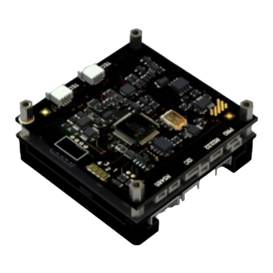
DX5100 Vision / User Guide PL Engineering Ltd DX5101 programming signals generation LED indication of the interfaces status and of programming signals status For external commutations there are connectors located on one side of the board. With the converter interface DX5104. - Page 12 PL Engineering Ltd DX5100 Vision / User Guide Now you must select the device to work with. The logic of the Program involves working with one controller at a time, so flags of the "command" interface choice work like radio buttons.
- Page 13 DX5100 Vision / User Guide PL Engineering Ltd If the RS-485 interface is "command", the choice of a "non- command"interface will not be available. Press the button "Open". After a successful communication, the program displays information about the controller, a version of the program used, and communication parameters.
-
Page 14: Setting Communication Parameters Of Controller Dx5100
PL Engineering Ltd DX5100 Vision / User Guide For the case when the RS-485 interface is "command", the possibility of selecting a device address in the network is added 3.3. Setting Communication Parameters of Controller DX5100 The protocol (WAKE) used to communicate with the Controller, supports addressing of devices from 1 to 127. - Page 15 DX5100 Vision / User Guide PL Engineering Ltd To configure the communication settings in the program the tab "Communication" is designed. It can be chosen either from the main menu or clicking the corresponding button in the toolbar. On this tab there are the controller settings for communication with the computer: •...
-
Page 16: How To Backup/Restore Of Parameters
PL Engineering Ltd DX5100 Vision / User Guide HOW TO BACKUP/RESTORE OF PARAMETERS The operating parameters of the controller, stored in nonvolatile memory of the digital control board, can be provided for the backup (storage) and, if necessary, restore. It is advisable to save the parameters before the procedures changing them, as well as after their completion. -
Page 17: Procedure Of Restoring From Backup
DX5100 Vision / User Guide PL Engineering Ltd The program suggests that you should save a file with the controller settings. The file name is proposed to be "Device information", but you can use another name. As a result of the procedure, the configuration file will be saved. -
Page 18: Additional Possibilities. Non-Volatile Memory
PL Engineering Ltd DX5100 Vision / User Guide 4.3. Additional Possibilities. Non-Volatile Memory In order to quickly estimate the Controller parameters that determine the logic of its operation, you can use the tab "non-volatile memory": page 18 of 68 ver. 1.04 (2017) - Page 19 DX5100 Vision / User Guide PL Engineering Ltd Functions of the buttons: • "Reload FLASH"- read data from the controller; • "Save to File"- save data to disk, with possibility to a later load, see the previous section; • "Load from File"- load the file, for viewing only, without the possibility of storage in the controller.
- Page 20 PL Engineering Ltd DX5100 Vision / User Guide configuration to handle all possible thermistor nominals (see the documentation TEC Controller DX5100 Technical Manual Accuracy). 2.13 The figure shows the properly filled in structure of thermistor settings. The indication of the correct filling is the last byte in each row: if it is equal to 55h, the setup is made correctly, and you can use the default settings when selecting a thermistor.
-
Page 21: Setting Alarm Limits
DX5100 Vision / User Guide PL Engineering Ltd SETTING ALARM LIMITS 5.1. Setting Limits of TEC Voltage Important! To prevent a thermoelectric cooler (TEC) failure, it is necessary to set correct limit values of TEC voltage. Refer to the TEC specifications. - Page 22 PL Engineering Ltd DX5100 Vision / User Guide The tab "Limiting temperatures" allows you to specify the maximum and minimum temperatures. If temperature is beyond these limits within the time specified, a corresponding alarm is on and PID control is off, - the alarm conditions.
-
Page 23: Thermistor Setting
DX5100 Vision / User Guide PL Engineering Ltd THERMISTOR SETTING Attention! It is strongly recommended to back up the parameters of the controller before adjusting the thermistor. See "Backup/restore of parameters". 6.1. Description of Procedure The procedure consists of finding and storing parameters of the corresponding ADC channels in the non-volatile memory for each temperature sensor. -
Page 24: Determination Of Input Data
PL Engineering Ltd DX5100 Vision / User Guide calculation (or entering) coefficients, storage of coefficients in controller. • • Calibration of temperature measurement channel: Controller firmware version <= 333 calibrating resistors supplied should be used, cable of four-wire resistance measurement circuit. - Page 25 DX5100 Vision / User Guide PL Engineering Ltd If you have chosen a thermistor from the list, you can go to the next section, "Calibration of temperature measurement channel". You may check the results of calculations by using the button "Calc".
-
Page 26: Calibration Of Temperature Measurement Channel
PL Engineering Ltd DX5100 Vision / User Guide while the average - in the middle. The distance between points must be at least 10 degrees. When choosing a polynomial function of temperature calculation you are supposed to enter the coefficients. - Page 27 DX5100 Vision / User Guide PL Engineering Ltd Click the button "Calibrate". The program will ask for the confirmation. After the positive answer the calibration procedure is started. The program asks to connect the jumper in the place of the thermistor (the connector of the cable of the four-wire resistance measurement circuit).
- Page 28 PL Engineering Ltd DX5100 Vision / User Guide Set the jumper, click "Ok". The program will do the zero calibration and ask you to connect the calibration resistance of the closest nominal, but not greater than the value calculated. Connect the resistance 1500 Ohm (supplied). Click "Ok".
- Page 29 DX5100 Vision / User Guide PL Engineering Ltd Connect the resistor 750 Ohm. Click "Ok". The program will ask for the nominal value of the resistor connected again (Ohm). Write 750. Click "Ok". The procedure of setting the thermistor parameters and calibrating...
-
Page 30: Controller Firmware Version >= 334
PL Engineering Ltd DX5100 Vision / User Guide 6.3.2. Controller Firmware Version >= 334 Since the calibration procedure of the measurement channel has been carried out by the manufacturer, you need only select your thermistor type and value: After clicking the "Calibrate' button and confirming the start of the... -
Page 31: Viewing Current Settings Of Thermistor. Checking
DX5100 Vision / User Guide PL Engineering Ltd • The manual mode is described in Section4.3.1 • In the automatic mode, the parameters set in the controller will match your thermistor. 6.4. Viewing Current Settings Thermistor. Checking Measurements. If necessary, you can get the current thermistor settings and assess the accuracy of measurements. - Page 32 PL Engineering Ltd DX5100 Vision / User Guide If the coefficients are not identical (an unknown thermistor), the program will build a graph of temperature versus resistance, and determine the thermistor nominal by the obtained coefficients (for platinum thermistors at Т = 0 С, for NTC thermistors at Т...
-
Page 33: Verification Of The Function Of Temperature Calculation
DX5100 Vision / User Guide PL Engineering Ltd 6.4.1. Verification of the function of temperature calculation Using the input field for temperature or resistance in the block "Check function of approximation" you can verify if the calculated values agree with the experimental ones. - Page 34 PL Engineering Ltd DX5100 Vision / User Guide resistance values from the table, click the button "Calc". Repeat the calculation for each point of the original table. Obtain the results of temperature calculation: → Initial data Calculated T = f(R)
-
Page 35: Checking Temperature Measurement Channel
DX5100 Vision / User Guide PL Engineering Ltd 35670 35670 27230 27242 20960 20970 16260 16266 12710 12709 10000 10000 7920 7922 6320 6316 5070 5067 4090 4090 3320 3320 2710 2710 6.4.2. Checking Temperature Measurement Channel The block "Measurement of the resistance of the thermistor"... -
Page 36: Program Manager
PL Engineering Ltd DX5100 Vision / User Guide The controller applies a 24-bit ADC. Hence, the full scale (the nominal value of the resistance, which we entered in the calibration) corresponds to the value FFFFFFh. It should be close to this value, but not equal, otherwise it will be perceived as an overflow. - Page 37 DX5100 Vision / User Guide PL Engineering Ltd The tabs from 0 to 15 correspond to the programs in the controller, the green indicator on the tab of the program indicates that the program is available. The controller can auto-switch to this program...
- Page 38 PL Engineering Ltd DX5100 Vision / User Guide The first two fields "ProgramNum" and "LineNum" cannot be edited. The field "Val" is a field of the type float and stores the setpoint for the control command. The next field "Time" is the time, in seconds, during which the mode given in the line of the program will run.
-
Page 39: Autostart Configuration
DX5100 Vision / User Guide PL Engineering Ltd • The button "Save All" saves all the edited lines of the current program in the controller; • The button "Save current line" changes the current line in the controller. The edited lines are highlighted in yellow. The button is only available on the line changed. -
Page 40: Conditions Of Signaling Of Setpoint Attainment
PL Engineering Ltd DX5100 Vision / User Guide Temperature control PID-control Maintaining of constant voltage To select autostart, use the tab "Boot Mode". You can set necessary parameters for the different modes. The links provide reference information on possible modes of operation. - Page 41 DX5100 Vision / User Guide PL Engineering Ltd One can control and, if necessary, change the criteria for the set point achieved, by the tab "Criterion of Signal of Setting". The parameters to be entered: d1 - 2…255 - number of periods of PID, after which, if the...
-
Page 42: Digital Input Control (Dx5107)
PL Engineering Ltd DX5100 Vision / User Guide 10. DIGITAL INPUT CONTROL (DX5107) The board DX5107 When using the board DX5107 the controller can carry out the following: • Control of digital outputs, depending on temperature of the channel (each channel). The board has a relay that triggers after a certain period of time after reaching the desired temperature. - Page 43 DX5100 Vision / User Guide PL Engineering Ltd • Transition to programs of channel control by signals arriving at the digital input. That is, using an external influence the controller can be transferred into different modes of regulation. • Synchronization of the controller with the work of external devices, and external events processing.
-
Page 44: Pid Tuning
PL Engineering Ltd DX5100 Vision / User Guide The marks "Digital Input" and "Digital Output" allow or prohibit the use of the digital input-output. For each channel, you can enter the program number to control the operation whenever the input signal changes. -
Page 45: Ziegler-Nichols Algorithm
DX5100 Vision / User Guide PL Engineering Ltd This function realizes the known Ziegler-Nichols algorithm. The user applying this function can use the obtained PID controller parameters for the subsequent accurate adjustment or apply the given parameters directly to the control of the object. -
Page 46: Pid Tuning Tips
PL Engineering Ltd DX5100 Vision / User Guide τ Deadtime τ Process gain τ The found values of the specified parameters by the Ziegler-Nichols method enable to estimate the PID parameters as: 1,2 х K Proportional coefficient τ Integral coefficient τ... - Page 47 DX5100 Vision / User Guide PL Engineering Ltd Kp1>Kp2>Kp3>Kp4>Kp5 Ttarget Modify the value of the differential component factor so that the form of the transitive characteristic correspond that of curve 2. Ttarget The integrated component is intended to remove a residual mismatch between the temperature value achieved in the system and the setpoint.
-
Page 48: Terminal
PL Engineering Ltd DX5100 Vision / User Guide 12. TERMINAL 12.1. How to Communicate with Controller via System of Commands For a maximum flexibility, the controller gives an opportunity of communicating in the terminal mode. For example, you can develop your own model of the controller behavior, regulation using various input parameters;... -
Page 49: How To Save Sets Of Commands In File
DX5100 Vision / User Guide PL Engineering Ltd In the upper right window of the edit box specify the address of the controller and the extended address. The controller DX5100 extended address is always 0200. In the next entry field you can enter commands sent to the controller... -
Page 50: Conversion Of Files With Commands From Program "Terminal
Conversion of Files with Commands from Program "Terminal" If you previously used the program "Terminal" you may have saved command files of the old format (*.ini). In this case, you can convert them for the use in DX5100 Vision. page 50 of 68 ver. 1.04 (2017) -
Page 51: Usage Of Set Of Commands As Macros
DX5100 Vision / User Guide PL Engineering Ltd 12.4. Usage of Set of Commands as Macros You can execute single commands, and can mark necessary commands, set the delay time (duration in milliseconds after the command execution) and click on the Start button on the right toolbar. -
Page 52: Cyclic Execution Of Macros
PL Engineering Ltd DX5100 Vision / User Guide The commands will be executed sequentially from top to bottom. 12.5. Cyclic execution of Macros. You can also perform sets of commands in cycle. To do it, it is necessary to click the button "Run macro as cycle" and then "Start macro". -
Page 53: Monitor
DX5100 Vision / User Guide PL Engineering Ltd 13. MONITOR 13.1. Telemetry Start The program ha the following modes: monitoring the current status of the controller, telemetry by a user's choice, charting, data storage for later analysis. The monitor window is not for parameters setting. You can only receive information from the controller and control the current behavior and regulation by one or two channels. -
Page 54: Choice Of Regulation Mode
PL Engineering Ltd DX5100 Vision / User Guide command interface , the choice is not available and the telemetry speed will be lower. The telemetry period is the interval at which the controller will generate telemetry data. It can take the values from 1 to 255, 1 corresponds to 10 ms. - Page 55 DX5100 Vision / User Guide PL Engineering Ltd • Mode "Program": • Mode "T-regulation": • Mode of PID temperature control: Starting with the controller version DX5100.333 it is possible to change a temperature setpoint without restarting PID: ver. 1.04 (2017)
-
Page 56: Charts
PL Engineering Ltd DX5100 Vision / User Guide Request for setpoint: • Mode "Constant voltage": See the Chapter "5.1 Setting Limits of TEC Voltage" 13.3. Charts It is possible to build two graphs simultaneously; the choice of parameters for each graph is done from the drop-down list: page 56 of 68 ver. - Page 57 DX5100 Vision / User Guide PL Engineering Ltd Each chart has its own toolbar: "+" "-" • buttons allow minimizing/maximizing the chart window: • Next button is zooming (the default chart width is 200 pixels): ver. 1.04 (2017) page 57 of 68...
- Page 58 PL Engineering Ltd DX5100 Vision / User Guide • Button of scale recovery (200 pixels): • Storage button saves the data to an Excel file: page 58 of 68 ver. 1.04 (2017)
-
Page 59: Status Bar
For feedback you can use the form "About". We are always glad to offer you all the possible assistance. 14.1. Software Update The update of DX5100 Vision program is available in the window "About". Or on our web: http://www.promln.ru/downloads/ 14.2. -
Page 60: How To Prepare For Controller Programming
PL Engineering Ltd DX5100 Vision / User Guide Here are the steps that are necessary for the successful programming of the controller: 14.2.1. How to Prepare for Controller Programming • Turn off the controller power; • Set the jumper supplied to the connector "PRG";... -
Page 61: Programming
DX5100 Vision / User Guide PL Engineering Ltd Select the version of the file; Proceed to the next page of the wizard; 14.2.3. Programming ver. 1.04 (2017) page 61 of 68... - Page 62 PL Engineering Ltd DX5100 Vision / User Guide Attention! Turn on the controller power If you want to change the serial port number and speed of programming, press the button "Start". Proceed to the next page of the wizard; page 62 of 68...
-
Page 63: How To Set Connection Rate In Controller After Programming
DX5100 Vision / User Guide PL Engineering Ltd 14.2.4. How to Set Connection Rate in Controller after Programming After programming the controller, the setting of the connection rate may have changed. There is a special procedure of setting new parameters: Remove the jumper, reset the controller, select the speed you are going to use in future to work with the controller. - Page 64 PL Engineering Ltd DX5100 Vision / User Guide page 64 of 68 ver. 1.04 (2017)
- Page 65 DX5100 Vision / User Guide PL Engineering Ltd ver. 1.04 (2017) page 65 of 68...
- Page 66 PL Engineering Ltd DX5100 Vision / User Guide page 66 of 68 ver. 1.04 (2017)
- Page 67 DX5100 Vision / User Guide PL Engineering Ltd ver. 1.04 (2017) page 67 of 68...
- Page 68 PL Engineering Ltd DX5100 Vision / User Guide Overseas Sales representative PL Engineering Ltd. TEC Microsystems GmbH 46 Warshawskoe shosee Schwarzschildstrasse 8 Moscow 115230 Russia Berlin 12489, Germany phone: +49-(0)30-6789-3314 e-mail: info@promln.com fax: +49-(0)30-6789-3315 phone: +7-499-678-3231 e-mail: info@tec-microsystems.com website:www.tec-microsystems.de page 68 of 68 ver.
Need help?
Do you have a question about the DX5100 Vision and is the answer not in the manual?
Questions and answers