
Subscribe to Our Youtube Channel
Summary of Contents for TGB BLADE 550i IRS 4X4
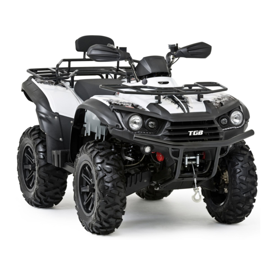
- Page 1 ONE / TWO - UP BLADE 550i IRS 4X4 BLADE 550i EPS IRS 4X4 BLADE 550i EPS SE IRS 4X4 Recreation Utility Vehicle Assembly Manual...
- Page 2 The procedures below are described in the information required for the correct assembly order that the procedures are carried out of this TGB vehicle prior to delivery to the correctly and completely. Failure to do so can customer. Since some external parts of the...
-
Page 3: Table Of Contents
Table of Contents PAGE CONTENT Symbols Used on Outer Cover Crate Handling Uncrating Parts Check Assembly (Shock Absorber) Assembly (Wheels) Assembly (Handlebar) Assembly (Speedometer) Assembly (Shift Lever) Assembly (Rear Carrier) Assembly (Battery) -
Page 4: Symbols Used On Outer Cover
Symbols Used on Outer Cover (1) Indicates correct upright position of the transport package. (2) Transport package must be kept away from rain. (3) Contents of the transport package are fragile, therefore the package must be handled with care. (4) Up to 4 of the transport packages can be piled up. (5) Do not insert from the symbol position of the transport package. -
Page 5: Crate Handling
Crate Handling Warning 1. Always handling the crated vehicle by a forklift, include stacking/un-stacking and storing. 2. Never stacking up over the indicated high shown on the crate outer cover. Caution 1. Insert the fork according to the indication position where shown on the crate outer cover. 2. - Page 6 2. Remove top cage braces (C), and be careful to avoid damage to the vehicle plastics and the seat leather during the action. 3. Remove the bolts (D), and then lay down LH & RH side diagonal braces (E) to disengage its sockets from the pallet.
-
Page 7: Parts Check
Parts Check Note There may be minor differences in appearance between these illustrations and the actual vehicle parts. Remove the parts and check the crate base and packaged materials carefully for lost parts. Check the parts against the illustrations. In the following charts under Remarks, D=diameter in millimeters, and L=length in millimeters, and P=Pitch. - Page 8 FOR 2-UP MODEL Part Name Remark Front Wheel Assy. AT 25 x 8 - 12 or AT 26 x 8 - 14 Rear Wheel Assy. AT 25 x 10 - 12 or AT 26 x 10 - 14 Wheel Nut Rubber Cap Battery 12V 18AH...
- Page 9 Part Name Remark Shift Lever Holder Spring Shift Lever Pull Rod Assy. Bolt D=5, L=8 Owner’s Manual Tool Bag Shock Absorber Bolts D=10, L=48, P=1.25 Shock Absorber Nuts D=10, P=1.25 Speedometer Bracket Bolts D=6, L=16, P=1.0 Right Glove Box Cover Left Glove Box Cover...
-
Page 10: Assembly (Shock Absorber)
Assembly After opening the crate, lift the vehicle out from the packing crate, and place the vehicle on a suitable rack, or using jacks to raise the vehicle for assembling process. Warning Torque wrench tightening specifications must be adhered to. Warning 1. - Page 11 3. Wheels Install the wheel, make sure the air valve is facing out, and the arrow mark (if exist) on the tire point toward to rotating direction of the wheel. Tighten the nuts (C) with 680~720 kgf-cm tighten torque and then plug the rubber cap (D).
- Page 12 6. Shift Lever Insert the pull rod assy. (K) into the gear shifter shaft, placed the spring (L) and lever holder (M) into the shaft, and push the holder down until the fixing bolt (N) can be thread in and tighten. 7.
Need help?
Do you have a question about the BLADE 550i IRS 4X4 and is the answer not in the manual?
Questions and answers