
Related Manuals for Dante tecnare DAV-4x500

Summary of Contents for Dante tecnare DAV-4x500
- Page 1 Operation Manual DAV-4x500 Version 1.1 (Firm. 1.02.04 and above) Four Channels Digital Amplifier Volt Constant Keep these important operating instructions. Available Check www.tecnare.com for updates.
- Page 3 General Information DVA4x500 Operation Manual Ver.: 1.1_UK 09/2020 ©EXEL ACOUSTICS SL; all right reserved The information contained in this manual has been carefully checked for accuracy, at the time of going to press, however no guarantee is given with respect to the correctness. Exel Acoustics SL accepts no responsibility for any errors or inaccuracies that may appear in this manual or the products and software described in it.
-
Page 4: Important Safe Instructions
Operation Manual IMPORTANT SAFE INSTRUCTIONS Before using our product, be sure to carefully read the manual and safe Instructions. Keep this document with the device all time. posed to rain or moisture, does not operate normally, Read these instructions or has been dropped. Keep these instructions. -
Page 5: Importantes Instrucciones De Seguridad
Operation Manual IMPORTANTES INSTRUCCIONES DE SEGURIDAD Antes de usar este producto, asegúrese de leer cuidadosamente el manual y las instrucciones de seguridad. el aparato ha sido expuesto a lluvia o a la humedad, Lea estas instrucciones. no funciona con normalidad o se ha caído. Conserve estas instrucciones. -
Page 6: Symbol Used
Operation Manual SYMBOL USED Dangerous voltages; risk of Important operating Frame or chassis Protective earth ground electrical shock instructions Pour indiquer les risques resultant de tensions dange- Pour indequer important Masse, chassis Terre de protection reuses Instructions Warnung vor gefährlicher Wichtige Betriebsanweisung elektrischer Spannung oder Gebrauchsanleitung... -
Page 7: Standards
Operation Manual STANDARDS FOR CUSTOMERS IN EUROPE This product complies with both the LVD (electrical safety) 73/23/EEC and EMC (electromag- netic compatibility) 89/336/EEC directives issues by the commission of the European com- munity. Compliance with these directives implies conformity with the following European standards: EN60065 Product safety EN55103-1... - Page 8 Operation Manual FCC Caution: Any changes or modifications not expressly approved by the party responsible for compliance could void the user’s authority to operate this equipment. FOR CUSTOMERS IN THE CANADA This product complies with CA /CSA C22.2 No.60065-03 Ce produit est conforme avec CA /CSA C22.2 No.60065-03 THIS PRODUCT MUST BE EARTHED.
-
Page 9: Declaración De Conformidad
Operation Manual DECLARACIÓN DE CONFORMIDAD DECLARATION OF CONFORMITY EXEL ACOUSTICS SL CL Encinar, 282. Polígono Industrial Monte Boyal. 45950 – Casarrubios del Monte (Toledo), España (Spain). Declara que el amplificador DVA4x500 y sus respectivas opciones, cumple con los objetivos de las Directivas: Declare under our sole responsibility that the DVA4x500 amplifier products comply with relating Directives: (1) Directiva de Baja Tensión - 2014/35/UE (2) Directiva de Compatibilidad Electromagnética - 2014/30/UE... -
Page 10: Table Of Contents
Table of Contents DAV-4x500 Table of Contents IMPORTANT SAFE INSTRUCTIONS ______________________________ 4 IMPORTANTES INSTRUCCIONES DE SEGURIDAD _________________ 5 SYMBOL USED _______________________________________________ 6 STANDARDS _________________________________________________ 7 DECLARACIÓN DE CONFORMIDAD _____________________________ 9 DECLARATION OF CONFORMITY _______________________________ 9 1. Welcome and unpacking ______________________________________ 11 1.1. -
Page 11: Welcome And Unpacking
Welcome DAV-4x500 1. Welcome and unpacking 1.1. Welcome to Tecnare ® DVA4x500 DSP Amplifier System for your aplication. Thank you for choosing a Tecnare Please spare a little time to study the contents of this manual, so that you obtain the best possible performance from this unit. -
Page 12: Introduction And Key Features
2.2. Key features ® • DANTE network audio optional • Network TCP / IP control, can realize management of multiple devices •... -
Page 13: Front And Rear Panel
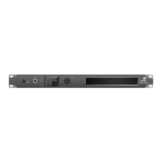
Introduction DAV-4x500 2.3. Front and Rear Panel Fig. 1 Front and rear panel The DVA4x500 DSP amplifier system is designed to be mounted in a standard 19”/1HU rack enclo- sure. Where the amplifier is used in a fixed installation, it is possible to use only the front panel 19” rack mounting holes to mount it in a standard rack enclosure. -
Page 14: Ac Power Connection
Introduction DAV-4x500 2.4. AC Power Connection The amplifier must always be connected using a 3-wire, grounded AC supply. The framework of the rack mount enclosure should also be connected to the same grounding circuit. The unit should never be operated unless the AC power cable ground is correctly terminated;... - Page 15 Introduction DAV-4x500 as shown in Figure 03. Input XLR unbalanced connection Pin 2 HOT + Pin 1 Shield Fig. 03: Balanced to Unbalanced Analogue wiring and PIN out. 2.5.3. Amplifier Output Connections The DVA4x500 amplifier is fitted with a twin high-current, color-coded binding posts (for Banana connector, spade lugs or bare wire) per output amplifier channel.
-
Page 16: Display Interface
Display DAV-4x500 3. Display Interface 3.1. Status Screen Fig. 06 Status Screen Fig. 07 a.- Device conected to the software; b.-Output limiter working 3.2. Main Menu Enter the MAIN MENU by pressing the SELECT button at the right of the display with just one click. From the MAIN MENU one may navigate, rotating the encoder button, to one of eight other menus. - Page 17 Display DAV-4x500 Fig. 10. 10-a Sub menu 2: Sensitivity; 10-b Sub menu 3: Preset Fig. 11. 11-a Sub menu 6: Rename Device; 11-b Sub menu 8: Ifo Device Fig. 12. Sub menu 4: Status Device DAV-4x500 Amplifier | rev.:1.1 w w w . t e c n a r e . c o m...
-
Page 18: Software Installation
Software installation DAV-4x500 4. Software installation 4.1. PC software introduction Equipment M_Console software is software for users to quickly interact with each parameter of one or more devices. The configuration parameters of the device can be stored in a disk file, which provides a very con- venient method for presetting the scene configuration and parameter switching and restoration of multiple devices or different use places. -
Page 19: Software Interface Description
Software Installation DAV-4x500 IMPORTANT: Some connection methods do not support multiple PCs being opened at the same time. Please keep at most one PC open this software 4.3. Software interface description Fig. 14 Main interface software 4.3.1. Module of main interface of the software 1. -
Page 20: Device Information
Software Installation DAV-4x500 4.5. Device Information 1. As shown in the figure the device name, group, and IP can be modified. Modification method: find the “Device” menu in the upper menu bar, and then make click in “Devices” in the Device context menu. A “Device Manage” screen will appear. -
Page 21: Amplifier Status
Software Installation DAV-4x500 4.7. Amplifier Status Fig. 23 Amplifier Status The amplifier status view allows you to see and set the limiter and impedance as required. When the limiter is on, the overload lamp will light up. 4.8. Menus The menu sytem is arranged like so: 4.8.1. -
Page 22: Scanning
Software Installation DAV-4x500 5. Disconnect all devices: Goes offline all the devices to the network. 4.8.4. Preset Using the Preset menu option, you can manage the settings of the device. 1. Save: Select “save” to store all the current parameters of the device to the device memory. -
Page 23: Setting
Software Installation DAV-4x500 4.10. Setting It will set the connection mode of the scanning device. Click the “Settings” button, and the port con- nection interface will appear as shown in Figure 30.Then, select the corresponding mode and set the corresponding parameters to confirm. - Page 24 Software Installation DAV-4x500 Fig.32 Network’s IP address w w w . t e c n a r e . c o m DAV-4x500 Amplifier | rev.:1.1...
-
Page 25: Function Module Interface
Function Module Interface DAV-4x500 5. Function Module Interface In order to facilitate the interaction of different parameters of the device, the software is divided into multiple modules according to the functional order. If the user wants to operate the corresponding module, he can use this module control key to open, close, and locate the module interface. -
Page 26: Input Module
Function Module Interface DAV-4x500 5.2. Input Module Double-click on the module button, the channel input module will shown. A new window whith the input detail will appears. As shown in Figure 35, you can operate the polarity, mute, and input source sensitiv- ity in the corresponding input channel. -
Page 27: Input Eq
Function Module Interface DAV-4x500 5.4. Input EQ Double-click on the module button, the following figure 38, input equalizer setting module, will appear. The button in the upper right corner of the module can enlarge this module, and the interface display will be clearer after being enlarged. -
Page 28: Matrix Mixing
Function Module Interface DAV-4x500 Select the corresponding preset in the preset list on the left, and then click the function button on the right to archive, recall, delete, and rename the equalizer setting parameters.s to test the channel according to your own requirements in the test signal settings. -
Page 29: Output Compressor
Function Module Interface DAV-4x500 5.8. Output Compressor Double-click on the compressor module button and will appear the figure 42, Output com- pressor setting module. Fig. 42 Output Compressor Setting Module 5.9. Output Limiter Double-click on the limiter module button and will appear the figure 43, Output Limiter setting module Fig. -
Page 30: Input & Output Interface
Input & Output Interface DAV-4x500 6. Input & Output Interface The following plots show direct access from the input and output interface available within the M_ Console Software. Fig. 45 Input & Output interface 6.1. Input Channel The input channel interface from top to bottom includes: Channel name, Input mode, Channel gain, Function buttons, and Channel group joint debugging. - Page 31 Input & Output Interface DAV-4x500 The channel group joint tuning situation shows the default 4 channel joint tuning group. When the background of the corresponding number box turns yellow , it means that this channel has been added to the second group for joint tuning.
-
Page 32: Device List
Device List DAV-4x500 7. Device List Fig 47 Device List In the figure 47, you will find the number of devices on the connection, the device’s names and the factory names (the user cannot modify it). If the connection method is TCP, the network IP address of this device will be displayed in the space to the left of the factory name after connecting. -
Page 33: Channel Name Management
Device List DAV-4x500 As shown in the plot 49, the device information displayed on the target device management interfa- ce can be selected in the device list at the top. The device management interface is divided into the following three blocks: Software information: Display the version number and date information of the upper and lower computer of the current device. -
Page 34: Firmware Upgrade
Device List DAV-4x500 7.5. Firmware upgrade To update the firmware in the device, click “System” -> ”Upgrade” in the menu bar of the software main interface, and the firmware upgrade interface will appear, Figure 52. Firmware is the software which runs inside the device. DAV-4x500 have firmwa- re which can be updated by the user. -
Page 35: Technical Specifications
Technical Specifications DAV-4x500 8. Technical Specifications AUDIO Input impedance 10k balanced Max Input level 6dB: +16dBu Frequency Response 20Hz - 20kHz+/-0.5dB @ 1W, 8 Ohm load THD+Noise <0.1% @1W-full power 6dBu: 94dB; 0dBu: 94dB Channel Isolation <-70dB PROTECTION SYSTEMS DSP limiter, Output over/under current/ voltage, Over temperature, High-Frequency, short circuit, back EMF, Surge current limiter, Switch on surge (Soft-start current inrush limiting), DC on output, power circuit breaker protection. - Page 36 Network (input & link) and Com. 2x RJ45 socket; TCP/IP, 1000base-T/100base-TX RS485/RS232 GPIO ® Audio Network (DANTE 2x RJ45 socket REGULATORY COMPLIANCE This product complies with the EMC & LVD directives as issued by the Commission of the European Community.
- Page 37 DAV-4x500 Reinventing The Rules ©2020 Tecnare Sound Systems. All rights reserved. DAV-4x500 Operation manual The contents of this manual are furnished for informational purposes only, are subject to change without notice, and should not be construed as a commitment by Exel Acoustics SL. Exel Acoustics assumes no responsibility or liability for any errors or in- accuracies that may appear in this manual.
- Page 38 EXEL ACOUSTICS SL CL Encinar, 282 - Pol. Ind. Monte Boyal 45950 Casarrubios del Monte (To) Spain (e): support@tecnare.com M_Console™ www.tecnare.com - www.facebok.com/tecnare (T): +34 918 170 110 - +34 918 171 001 (F): +34 918 183 053 rev. 1.1 2020...
Need help?
Do you have a question about the tecnare DAV-4x500 and is the answer not in the manual?
Questions and answers