Table of Contents
Advertisement
Quick Links
Section 1
System Description
TunnelTech 500/700 Series
Operating and Maintenance Manual
Tunnel Atmosphere Monitoring System
(CO/NO/NO
/Vis)
2
CODEL International Ltd.
Unit 4, Station Road, Bakewell, Derbyshire DE45 1GE United Kingdom
t : +44 (0) 1629 814 351
f : +44 (0) 8700 566 307
e : codel@codel.co.uk
web : www.codel.co.uk
Page: 1
Issue: A
Revision: 10
Date: 10/01/22
Ref: 100575
Advertisement
Table of Contents

Related Manuals for Forbes Marshall CODEL TunnelTech 500 Series

Summary of Contents for Forbes Marshall CODEL TunnelTech 500 Series
- Page 1 Section 1 System Description TunnelTech 500/700 Series Operating and Maintenance Manual Tunnel Atmosphere Monitoring System (CO/NO/NO /Vis) CODEL International Ltd. Unit 4, Station Road, Bakewell, Derbyshire DE45 1GE United Kingdom t : +44 (0) 1629 814 351 f : +44 (0) 8700 566 307 e : codel@codel.co.uk web : www.codel.co.uk Page: 1...
- Page 2 TunnelTech500/700 Operating-and-Maintenance-Manual Page: 2...
- Page 3 Section 1 System Description CODEL International Ltd is a UK company based in the heart of the Peak District National Park at Bakewell, Derbyshire. The company specialises in the design and manufacture of high-technology instrumentation for the monitoring of combustion processes and atmospheric pollutant emissions. The constant search for new products and existing product improvement keeps CODEL one step ahead.
- Page 4 TunnelTech500/700 Operating-and-Maintenance-Manual Page: 4...
-
Page 5: Table Of Contents
Section 1 System Description Contents SYSTEM DESCRIPTION ....................9 500/700 S ................9 UNNEL ERIES 500 - CO, NO NO2 A ......10 UNNEL UALITY ONITOR 700 - CO, NO, NO .... 11 UNNEL ISIBILITY UALITY ONITOR 500 V ..................13 UNNEL ERSIONS 1.4.1 TunnelTech 500 Series: (Aluminium) ............ - Page 6 TunnelTech500/700 Operating-and-Maintenance-Manual ......................35 IME AND (TT700 ) ............37 ISIBILITY OMMISSIONING ONLY 5.3.1 Visibility Module Communication: .............. 37 5.3.2 Transmissometer Alignment: ................ 38 5.3.3 Final Alignment: ....................40 5.3.4 Transmissometer Detector Level Setup: ........... 42 5.3.5 Visibility Zero Calibration:................44 ..................
- Page 7 Section 1 System Description 10.1.2 Custom ......................75 APPENDIX 3 – INTERNAL ADDRESS NUMBERS ..........76 APPENDIX 4 – OPTIONAL HEATED MIRRORS ..........77 ............... 77 RRANGEMENT AND CONNECTIONS 12.1.1 Arrangement: ..................... 77 12.1.2 Connections: ....................... 77 APPENDIX 5 – MEMORY MAP ................80 ....................
- Page 8 TunnelTech500/700 Operating-and-Maintenance-Manual IMPORTANT The warning signs (and meanings) shown below, are used throughout these instructions and are intended to ensure your safety while carrying out installation, operation and maintenance procedures. Please read these instructions fully before proceeding. Caution, risk of electric shock. Caution, risk of danger.
-
Page 9: System Description
Section 1 System Description 1 System Description The TunnelTech 700 setup shown in figure 1 uses visible light to measure visibility and electrochemical cells to measure gases such as CO, NO, NO The TunnelTech 700 consists of a transceiver that projects visible light beam to a reflector unit mounted 3m away. -
Page 10: Co, No And No2 Air Quality Monitor
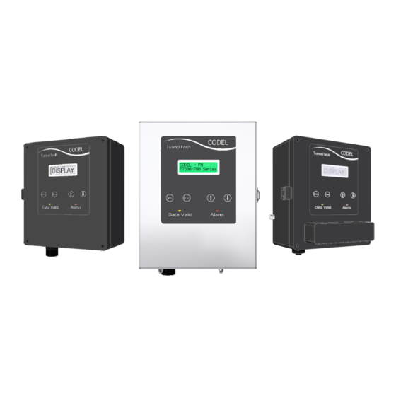
TunnelTech500/700 Operating-and-Maintenance-Manual TunnelTech 500 - CO, NO and NO2 Air Quality Monitor The monitoring stations provide all required measurements and outputs at each monitoring location within the tunnel. Modbus, Mains Supply current & analogue outputs Figure 1: TunnelTech 500 Monitor Stations 24V DC The TunnelTech 500 setup shown in figure 1 uses visible light to measure visibility and electrochemical cells to measure gases such as CO, NO, NO2. -
Page 11: And Visibility Air Quality Monitor
Section 1 System Description TunnelTech 700 - CO, NO, , and Visibility Air Quality Monitor The monitoring stations provide all required measurements and outputs at each monitoring location within the tunnel. Transceiver Mirror Modbus, Mains Supply current & analogue outputs Figure 2: TunnelTech 24V DC... - Page 12 TunnelTech500/700 Operating-and-Maintenance-Manual is linear and proportional to the ppm or ppb reading. A serial data link via an RS485 interface allows communication directly with the TunnelTech 700 sensors. All varieties of TunnelTech 700 and 710 are mounted using the same method, and both aluminium and stainless-steel brackets are made to the same dimensions.
-
Page 13: Co, No, No
Section 1 System Description TunnelTech 500 Versions 1.4.1 TunnelTech 500 Series: Model No. PCB Boards (Aluminium) NO² Display ✓ ✓ ✓ ✓ 501mA ✓ ✓ ✓ ✓ ✓ ✓ ✓ 502mA ✓ ✓ ✓ ✓ ✓ 503mA ✓ ✓ ✓ ✓... -
Page 14: Tunneltech 700 Versions
TunnelTech500/700 Operating-and-Maintenance-Manual TunnelTech 700 versions 1.5.1 TunnelTech 700 Series: Model No. PCB Boards (Aluminium) NO² Display ✓ ✓ ✓ ✓ ✓ 701mA ✓ ✓ ✓ ✓ ✓ ✓ ✓ ✓ ✓ 702mA ✓ ✓ ✓ ✓ ✓ ✓ ✓ 703mA ✓... -
Page 15: Power Supply
Section 1 System Description Power Supply A PSU is required to convert the mains (90-263V AC) supply to the 24V DC required to power the TunnelTech 700. Mains Input 24V DC Connection Earthing bolt Figure 5: Codel 24V DC Power Supply Unit 24V DC outputs Page: 15... -
Page 16: Principles Of Operation
TunnelTech500/700 Operating-and-Maintenance-Manual 2 Principles of Operation Electro-Chemical Cell: In order to measure the level of gas (CO/NO/NO ), the Tunnel Tech 700 uses an electro chemical cell to convert the gas in to readable data. The gas diffuses into the sensor and interacts with the electrode within the cell. This causes a chemical reaction in which the gas is reduced or oxidised. -
Page 17: Technical Data
Section 3 Specification 3 Specification Technical data: VIS (TT700 only) E-Cell Measurement type: Visibility Measurement principle: Optical Electrochemical Cell Transmissometry Measurement units: % or K factor (m Nominal Measurement range 0 to 100 % 0 to 800 ppm 0 to 160 ppm 0 to 10000 ppb (typical): 0 to 8.6 % or 0 to... -
Page 18: Construction And Enclosure
TunnelTech500/700 Operating-and-Maintenance-Manual Construction and Enclosure Aluminium Stainless Steel (Optional) Stainless Steel 316L Construction: Epoxy Coated Die-Cast Aluminium or Stainless Steel 316Ti Silver/ stainless steel Colour/Finish: Black (RAL 9005 - Jet Black) (Aluminium) (220-240 grit dull polished) Enclosure Rating: Designed to IP66 (IP69K Optional) Designed to IP66 Weight: 4.5 kg (15 Kg with brackets) -
Page 19: Optional Items
Section 3 Specification Optional Items: 24V DC Power Supply Input: 110 - 240V AC @ 100W Max., 50/60 Hz Output: 24V DC @ 60W Dimension: 200 (L) x 230 (H) x 110 (D) (mm) Colour: Black (RAL9005 - Jet Black) Construction: Die-cast Aluminium Enclosure Rating:... -
Page 20: Cables: (Recommended Minimum Specification)
TunnelTech500/700 Operating-and-Maintenance-Manual Cables: (Recommended Minimum Specification) Power Supply Cable: Shielding: Shielded to enclosure Cores / Wire Diameter: 2 Core / 1mm² Typically Supplied by: Customer RS485 ModBUS Cable: Shielding: Shielded away from enclosure Cores / Wire Diameter: 2 Core / 0.5mm² Typically Supplied by: Customer Analogue Output Cable:... -
Page 21: Tunneltech 700 Installation Material
Section 3 Specification TunnelTech 700 Installation Material Brackets: Aluminium Stainless Steel (Optional) Weight: 6kg (per bracket) 12kg (per bracket) Dimensions: 400 (L) x 300 (H) x 1220 (D) (mm) 400 (L) x 300 (H) x 1220 (D) (mm) Installation Bolts: Bracket: Free Air Tube Base... -
Page 22: Installation
TunnelTech500/700 Operating-and-Maintenance-Manual 4 Installation Dimensions & Mounting Details 4.1.1 tunnelTech 500 (Aluminium) Cable gland holes (tapped) are fitted with M20x1.5 blanking plugs as standard. Aproximatly 150mm of free space is required below the cable glands for safe cable insertion. Page: 22... -
Page 23: Mounting Details (Stainless Steel)
Section 4 Installation 4.1.2 Mounting Details (Stainless steel) Cable gland holes (tapped) are fitted with M20x1.5 blanking plugs as standard. Aproximatly 150mm of free space is required below the cable glands for safe cable insertion. Page: 23 Issue: A Revision: 10 Date: 10/01/22 Ref: 100575... -
Page 24: Tunneltech 700 Series
TunnelTech500/700 Operating-and-Maintenance-Manual 4.1.3 TunnelTech 700 series: Cable gland holes (tapped) are fitted with M20x1.5 blanking plugs as standard. Aproximatly 150mm of free space is required below the cable glands for safe cable insertion. Page: 24... -
Page 25: Tunneltech 708: (Vis Only)
Section 4 Installation 4.1.4 TunnelTech 708: (Vis only) Cable gland holes (tapped) are fitted with M20x1.5 blanking plugs as standard. Aproximatly 150mm of free space is required below the cable glands for safe cable insertion. Page: 25 Issue: A Revision: 10 Date: 10/01/22 Ref: 100575... -
Page 26: Tunneltech 710 Series: (Stainless Steel)
TunnelTech500/700 Operating-and-Maintenance-Manual 4.1.5 TunnelTech 710 series: (Stainless Steel) Cable gland holes (tapped) are fitted with M20x1.5 blanking plugs as standard. Aproximatly 150mm of free space is required below the cable glands for safe cable insertion. Page: 26... -
Page 27: Bracket Mounting Details
Section 4 Installation Bracket Mounting Details: The TunnelTech 700 is carried on fabricated mounting brackets (if supplied) and is WARNING: to be mounted on the side of the tunnel wall (or applicable surface) with a distance of 3 meters between the Vis lens, and reflection mirror (6meter folded beam) sure observe necessary safety precautions... - Page 28 TunnelTech500/700 Operating-and-Maintenance-Manual Attach the TunnelTech 700 AQM to the bracket via 3xM6 hex head screws (supplied), fastened from the free air tube side of the bracket. Observe the analyser’s location pins on the Visibility lens housing match the corresponding holes on the bracket for correct orientation. Page: 28 Figure 8: TT700 to Bracket...
-
Page 29: Power Supply Unit (Optional) Mounting Details
Section 4 Installation Power Supply Unit (Optional) Mounting Details Mount the PSU to the tunnel wall again using 4 x M6 bolts (customer supply). 180mm NOTE: Cover Base Cable glands are supplied by the customer according to the cables used during installation. -
Page 30: Connections
TunnelTech500/700 Operating-and-Maintenance-Manual Connections 4.4.1 TT500 The following electrical schematic illustrates the connections for the Tunnel Tech 500 Series system. WARNING: Wiring should only undertaken by a qualified technician. Electrochemical cell Address: 2 PCB 803-593 Serial Control/Display RS 485 Address: 1 PCB 803-584 Screen into monitor 24V DC... -
Page 31: Tt700
Section 4 Installation 4.4.2 TT700 The following electrical schematic illustrates the connections for a Tunnel Tech 701 system, with all available peripherals. Units that do not have certain elements shown below still maintain the same addresses. WARNING: Electrochemical Cell Address: 2 Wiring should only... -
Page 32: Power Connection
TunnelTech500/700 Operating-and-Maintenance-Manual 4.4.3 Power Connection: Place 24V screened cable through the gland and connect to CON1; 24V power input on the Display PCB (803-584-x). Figure 10: Power Connection 4.4.4 RS485 Connection: Attach a 3+PE cable to the cable gland socket fitted to the enclosure with Comms A wired to pin 1 and Comms B wired to pin 2. -
Page 33: Pcb Identification & Connections - Lid
Section 4 Installation 4.4.5 PCB Identification & Connections - Lid: Display PCB (803-584-x) Connection Description CON1 3-way 5.08mm Pluggable Terminal Block – to 24V CON1 DC power input PRG-A CON2 2-way 5.08mm Pluggable Terminal Block – to PRG-B Isolated RS485 Output. CON3 16-way IDC surface mount ribbon cable socket –... -
Page 34: Pcb Identification & Connections - Base
TunnelTech500/700 Operating-and-Maintenance-Manual 4.4.6 PCB Identification & Connections - Base: Visibility PCB (803-574-x) (TT700 only) Connection Description CON1 24V DC – NOT FITTED Visibility PCB CON2 RS485 – NOT FITTED CON3 16-way IDC surface mount ribbon cable socket – CON3 To mA PCB #1 (when applicable) PRG-A CON4 CON4... -
Page 35: Commissioning
Section 5 Commissioning 5 Commissioning Power Up After checking all the cable connections, switch on the mains power and wait for power-up sequence to complete and Data validity LED (green) to come on. When powered on, the display unit will come on displaying CODEL – FM (manufacturer’s name) and TT500/700 SERIES (instrument’s name). - Page 36 TunnelTech500/700 Operating-and-Maintenance-Manual Press the key on either time or date state. Pressing the keys, allows the user to adjust all fields within the set date / time menu with the key, moving to the next digit, unless on the final digit, moving to the next field to set time.
-
Page 37: Visibility Commissioning (Tt700 Only)
Section 5 Commissioning Visibility Commissioning (TT700 only) 5.3.1 Visibility Module To ensure that there is a working communication via the display unit; follow the Communication: steps below using the display. From the main display press the keys to reach Diagnostics. Press to access Diagnostic data. -
Page 38: Transmissometer Alignment
TunnelTech500/700 Operating-and-Maintenance-Manual 5.3.2 Transmissometer The AQM transceiver and reflector units should be mounted horizontally and Alignment: should be properly aligned for optimum performance. Initial alignment may be carried out by temporarily removing (but still supporting) 5.3.2.1 Without Alignment Laser: the body of the transceiver from its mounting bracket. Both transceiver and reflector units are equipped with universal adjustment features at the bottom of their respective mounting brackets. - Page 39 Section 5 Commissioning Firstly, ensure the laser point hits the reflector mirror in the centre, by looking down the reflector side free air tube. Figure 15: Reflector alignment 5.3.2.3 Alignment If the free air tube is not correctly aligned, the laser will not hit the centre of the Bracket Adjustment: reflector directly.
-
Page 40: Final Alignment
TunnelTech500/700 Operating-and-Maintenance-Manual Once the laser hits the centre of the reflector the device side tube is correctly aligned. Now check to ensure the reflector tube is correctly aligned by checking the position of the returning laser point. The laser will bounce off the mirror and should reflect directly back into the primary tube, and back on to the laser itself, if correctly aligned. - Page 41 Section 5 Commissioning From the main display press the keys to reach Diagnostics. Press to access Diagnostic data. Use the keys to reach Vis channel diagnostics, and press access. Use the keys to reach Vis DRx, and press to access. Observe the Vis DRx Smoothed value while adjusting the optical alignment of the instrument until this value has reached a plateau.
-
Page 42: Transmissometer Detector Level Setup
TunnelTech500/700 Operating-and-Maintenance-Manual 5.3.4 Transmissometer To edit and configure the levels and gains of the device firstly enter the “Setup Detector Level Setup: Mode” menu option and enter the subsequent “Sensor Setup and “Configure Vis” Menu options. 5.3.4.1 Alignment Process: 5.3.4.2 Auto Gains: To perform the auto detector level procedure, from the ‘Configure Vis’... - Page 43 Section 5 Commissioning 5.3.4.3 Manual Gains: In this menu there are options for manually altering the Vis Tx and Rx Gains. NOTE: If the values are set too high, the signal will go into saturation. Conversely if set too low, the data returned will be below a valid read level.
-
Page 44: Visibility Zero Calibration
TunnelTech500/700 Operating-and-Maintenance-Manual 5.3.5 Visibility To perform a zero calibration, firstly enter the ‘Setup Mode’ of the device menu Zero Calibration: and enter ‘Sensor Setup’, then the ‘Configure Vis’ menu option. NOTE: The system should only ever be zero calibrated in clean air, zero condition (fully ventilated with no traffic in the tunnel) To calibrate, select the visibility channel from the sensor setup mode menu and... -
Page 45: E-Cell Commissioning
Section 5 Commissioning E-Cell Commissioning 5.4.1 E-Cell Module To ensure that there is a working communication between the display unit and the Communication: electrochemical cell module, follow the steps below using the display. From the main display press the keys to reach Diagnostics. Press to access Diagnostic data. -
Page 46: Detector Levels
TunnelTech500/700 Operating-and-Maintenance-Manual 5.4.2 Detector Levels: From the menu position below the detector levels can be observed. In zero conditions the E-Cell detector levels should be: Approx. 26215 for CO (cell 1) ±500 Approx. 26215 for NO (cell 2) ±100 Approx. 32767 for NO (cell 3) ±100 The values that are given relate to the default starting values for the E-Cell channels. -
Page 47: Maintenance Due
Section 5 Commissioning 5.4.3 Maintenance Due: The maintenance Due date provides the user with information on when the E-Cell board in the TunnelTech 700 will need replacing. Make note of the maintenance date of the E-Cell. From the main display press to reach the Setup Mode menu and press to access the menu. -
Page 48: Ma Output Setup
TunnelTech500/700 Operating-and-Maintenance-Manual mA Output Setup The mA output menu allows the user to configure the measurand, zero and span information for the attached mA boards. In addition, the menu allows the user to simulate a given value on any attached board to test each individual channel. 5.6.1 Species Configuration: The first menu accessible Is the measurand selection menu, internally the system... -
Page 49: Ma Span Value
Section 5 Commissioning By pressing the key, the user can adjust the current value for the selected mA channel. Using the keys, manipulates the onscreen value with the moving to the next available location or setting the entered value if all 5 fields are complete. -
Page 50: Dac Zero / Span
TunnelTech500/700 Operating-and-Maintenance-Manual 5.6.4 DAC Zero / Span: The DAC (Digital Analog Converter) Zero and Span values must be calibrated during commissioning process to ensure accurate mA output values. 5.6.4.1 Simulate mA: To begin setting the DAC Zero or Span, firstly an mA simulation of 4mA or 20mA respectively must be set. - Page 51 Section 5 Commissioning If the value is not correct, the DAC Zero shall be altered, making small adjustments to the mA value until it reaches 4mA. Enter the DAC Zero submenu option of the mA output menu. NOTE: Increase the DAC Zero value increments, allow several seconds for the value...
- Page 52 TunnelTech500/700 Operating-and-Maintenance-Manual Enter the DAC Span submenu option of the mA output menu. NOTE: Whilst observing the multimeter / Druck value, alter the DAC Span value until 20.00mA is displayed. Press enter to set and return to the previous menu. Increase the DAC Span value increments, allow...
-
Page 53: Relay Output Setup
Section 5 Commissioning Relay Output Setup The relay output menu works in conjunction with the mA output menu, allowing the user to independently configure the relay measurand, direction and trigger level for each individual channel. 5.7.1 Relay Trigger Measurand: The first menu accessible Is the measurand selection menu, this menu displays the WARNING: measurand on which the alarm should trigger. - Page 54 TunnelTech500/700 Operating-and-Maintenance-Manual By pressing the key, the user can enter the configuration sub menu NOTE: If the measurand is not listed in the selection list the device displays “N/A” and treat the species with default Using the keys, the menu cycle’s through the available measurands. settings.
-
Page 55: Relay Direction
Section 5 Commissioning 5.7.2 Relay Direction: The relay system allows the user to configure if the relay channel is set to normally open or normally closed. This option is useful in fail-safe environments where power outages are common, forcing the connected relays to switch in case of power failure. -
Page 56: Maintenance
TunnelTech500/700 Operating-and-Maintenance-Manual 6 Maintenance The Tunnel Tech 700 Series system is designed for low maintenance. The sensors utilise the latest microprocessor technology and have no moving components. Visibility (TT700 only) 6.1.1 Mechanical Check: Every 6 months - clean the optical surfaces of the TunnelTech 700 sensor and the reflector unit. -
Page 57: Physical Alignment
Section 6 Maintenance The next stage of the mechanical check is to check detector levels. By following the steps below, observe the detector levels to see if they correspond with the required levels of 10000 +/- 200. From the measurements display press to reach Diagnostics. - Page 58 TunnelTech500/700 Operating-and-Maintenance-Manual to scroll from the main measurement’s menu to Vis% and press to select Vis%. The display returns to measurement screen displaying Vis% measurement. NOTE: Failure to carry out this check Place a check filter on the sight tube and observe the Vis % reading. Ensure to will invalidate the warranty observe the correct filter orientation, as this can affect the result.
-
Page 59: Electrochemical Cell
Section 6 Maintenance Electrochemical Cell A TunnelTech 708 or 718 does not contain Electrochemical Cells, as these devices are Vis only. 6.2.1 Mechanical Check: Depending on the conditions in the tunnel. Occasional cleaning of the E-Cell sintered filters is necessary. wipe clean with a soft dry cloth to remove any debris from the filters. - Page 60 TunnelTech500/700 Operating-and-Maintenance-Manual Remove the blank plug from the E-Cell block and connect a ¼” BSP to 6mm push- 6.2.2.2 Cal Gas Adaptor fit adapter. (Aluminium): Gas out through Attach ¼” BSP to 6mm Figure 20: Span Gas adapter sintered filters push-fit adapter here TunnelTech 700 6.2.2.3...
- Page 61 Section 6 Maintenance Before attaching the calibration gas adapter, ensure that the base of the enclosure around the sintered filters is free from any dirt or debris, using a soft dry cloth. Attach to the enclosure by placing the open end of the calibration gas adapter onto the bottom of the device over the sintered E-Cell filters, lining up the location pins with the guide holes on the enclosure.
-
Page 62: Zero Calibration
TunnelTech500/700 Operating-and-Maintenance-Manual 6.2.3 Zero Calibration: Connect a 100% Nitrogen bottle to the ¼” BSP to 6mm push-fit adapter / span kit (depending upon devices variation. See section 6.2.2.2 and 6.2.2.3). Set the flow rate to 1 litre per minute and wait for around 3 minutes. The level will be displayed on screen. -
Page 63: E-Cell Replacement
Section 6 Maintenance Press on the measurements menu and the following screen appears. Press to select the appropriate channel. The Display returns to measurement screen displaying the selected channel readings. Repeat these steps for the remaining gases. 6.2.4 E-Cell Replacement: The maintenance due date is an alarm hardcoded into the E-Cell board in the factory. - Page 64 TunnelTech500/700 Operating-and-Maintenance-Manual Remove the ribbon cable connecting the display/control board and the E-Cell board. There is no locking mechanism, and the ribbon cable will uncouple from its sockets when pulled away from the board. Figure 25: E-Cell Comms Ribbon Cable Remove the 6x nuts from the E-Cell, along with the washers, ensuring that these are kept safe for reinstalling the new PCB.
- Page 65 Section 6 Maintenance Figure 27: E-Cell Seal Removal If upon removal of the old E-Cell PCB, the sponge seals are attached to the enclosure, these must be removed carefully before the new board is installed. New E-Cell PCBs will arrive with sponge seals pre-attached to the Cells themselves. Insert the new E-Cell PCB into the unit, by lining up the cells on the PCB, with the machined holes in the enclosure lid, and the screw holes on the PCB with the 6 hex posts attached to the lid.
-
Page 66: Replacement E-Cell Pcbs
TunnelTech500/700 Operating-and-Maintenance-Manual Spare Parts 6.2.5 Replacement E-Cell Species Part number PCBs: 991.844 CO, NO 991.843 CO, NO, NO 991.842 991.845 NO, NO 991.848 991.846 mA/Relay Card: 803.604 Alignment Laser: 6.3.1 Optional Components: Serial USB-RS485 Interface cable 991.879 6.3.1.1 Vis Check filters: 1% - 991.528A 3% - 991.527A Figure 28: Spare Parts... -
Page 67: Data Communication
Section 7 Data Communication Data Communication Hardware Configuration 7.1.1 System: The PSU supplies power to the TunnelTech 700. The current and relay outputs of the device communicate measurement data to the tunnels' DCS system. RS485 Slave Display PCB RS485 E-Cell 9-36V Master Current Outputs... -
Page 68: Table Of Figures
TunnelTech500/700 Operating-and-Maintenance-Manual 8 Table of Figures 1: T 700 M ..............11 IGURE UNNEL ONITOR TATIONS 2: C 24V DC P ..............15 IGURE ODEL OWER UPPLY 3: T & R ............27 IGURE RANSCEIVER EFLECTOR OUNTING 4: B .................... 27 IGURE RACKET IMENSIONS... -
Page 69: Appendix 1: Rs485 Communications
Section 9 Appendix 1: RS485 Communications Appendix 1: RS485 Communications The TunnelTech 700 communicates via RS485 on the 4-way plug. All communications are in either standard MODBUS RTU or CODEL protocol. All instruments will be supplied with a 4-way black plastic plug. Connections in the plug are as follows: Figure 30: Comms Cable Connection... -
Page 70: Modbus Rtu Communication
TunnelTech500/700 Operating-and-Maintenance-Manual MODBUS RTU Communication The TunnelTech 700 implements standard MODBUS RTU function code 0x03 (Read Holding Registers) in order to access memory and retrieve values. The baud rate, number of data bits, parity and number of stop bits can be configured via the Display, please see the accompanying TunnelTech 700 Display Interface Manual (Document reference: 100577, section: 5.7 –... -
Page 71: Key Modbus Data Register Locations
Section 9 Appendix 1: RS485 Communications Key Modbus Data Register Locations CODEL Tunnel Tech 700 Series for Interrogation using Standard MODBUS Note that this is Standard Modbus protocol NOT Modbus Plus protocol. Reference: AEG Modicon Modbus Protocol Reference Guide PI-MBUS-300 Rev.D. Register Description Multiplication... -
Page 72: Configuring Rs485 Protocol & Addressing
TunnelTech500/700 Operating-and-Maintenance-Manual In order to configure the protocol and communications address used by the 9.2.1 Configuring RS485 Protocol & Addressing RS485 connection it is necessary to change a configuration register using MODBUS protocol. The first byte of the register corresponds to the communications protocol, which should be set to MODBUS in all normal operations, the valid values (in hexadecimal) are: 0x00 = CODEL Protocol... - Page 73 Section 9 Appendix 1: RS485 Communications Page: 73 Issue: A Revision: 10 Date: 10/01/22 Ref: 100575...
-
Page 74: Appendix 2 - Data Valid & Custom Relay Measurands
TunnelTech500/700 Operating-and-Maintenance-Manual Appendix 2 – Data Valid & Custom Relay Measurands This instrument can be configured to read any memory location and output that data as a relay alarm. This option is not part of the default output list that is accessible via display interface, but rather can be configured using the memory access with a PC via an RS485 connection running the CODEL Gateway software. -
Page 75: Custom
Section 10 Appendix 2 – Data Valid & Custom Relay Measurands 10.1.2 Custom From the Configure / Outputs tab, select “Custom” from the Alarm measurand dropdown box. NOTE: Please consult CODEL engineer before attempting to set a custom relay trigger once custom is selected, set the “Address”... -
Page 76: Appendix 3 - Internal Address Numbers
TunnelTech500/700 Operating-and-Maintenance-Manual Appendix 3 – Internal Address Numbers Address numbering is delegated to 2 UARTs. (Universal Asynchronous Receiver/Transmitter). The first UART is for external comms to the display unit on a network. The 2 UART is for internal communication to all peripheral devices, such as the E-Cell and Vis. -
Page 77: Appendix 4 - Optional Heated Mirrors
Section 12 Appendix 4 – Optional Heated Mirrors Display offset: RAM: 0x0C00 – 0x01FF Display offset: RAM: 0x1000 – 0x07FF 0x0C00 ROM: 0x2C00 – 0X2FFF 0x1000 ROM: 0x3000 – 0x33FF Appendix 4 – Optional Heated Mirrors Arrangement and connections 12.1.1 Arrangement: The mounting arrangement for the heated mirror assembly is shown below. - Page 78 TunnelTech500/700 Operating-and-Maintenance-Manual Page: 78...
- Page 79 : 10 Date: 10/01/22 Ref: 100575 Page: 79...
-
Page 80: Appendix 5 - Memory Map
Appendix 5 – Memory Map Memory Overview EEPROM TT700_DIS_RAM_MIN TT700_DIS_EEPROM_MIN 2000 TT700_DIS_RAM_MAX TT700_DIS_EEPROM_MAX 23FF TT700_VIS_RAM_MIN TT700_VIS_EEPROM_MIN 2400 TT700_VIS_RAM_MAX TT700_VIS_EEPROM_MAX 27FF TT700_ECELL_RAM_MIN TT700_ECELL_EEPROM_MIN 2800 TT700_ECELL_RAM_MAX TT700_ECELL_EEPROM_MAX 2BFF TT700_AN1_mA_RAM_MIN TT700_AN1_mA_EEPROM_MIN 2C00 TT700_AN1_mA_RAM_MAX TT700_AN1_mA_EEPROM_MAX 2FFF TT700_AN2_mA_RAM_MIN 1000 TT700_AN2_mA_EEPROM_MIN 3000 TT700_AN2_mA_RAM_MAX 13FF TT700_AN2_mA_EEPROM_MAX 33FF xxFF is unreadabale as it is an internal checksum. -
Page 81: Display Ram
Display RAM Modbus Modbus CODEL : Byte Offset (Hex) TTx00 Description Default Value Data Type Comment MemoryItem Address Register Address from Base Address (Hex) Type Ecell - 0000 LMP91000_1_Te ECELL_LMP1_TE 40001 mperature_RAM 0001 MP_RAM 0002 ChannelUnit_Cod ECELL_CHANNEL 40002 e_RAM 0003 UNIT_CODE_RAM Ecell - 0004... - Page 82 Modbus Modbus CODEL : Byte Offset (Hex) TTx00 Description Default Value Data Type Comment MemoryItem Address Register Address from Base Address (Hex) Type 0x17 0017 0x17 Ecell - 0x18 0018 0x18 CH2_DTx_Cal_Sm ECELL_CH2_DTX_ oothed_RAM_CO CAL_SMOOTHED 40013 0x19 0019 0x19 _RAM_COPY Ecell - ECELL_CH2_DTX_ 0x1A...
- Page 83 Modbus Modbus CODEL : Byte Offset (Hex) TTx00 Description Default Value Data Type Comment MemoryItem Address Register Address from Base Address (Hex) Type Ecell - ECELL_CH1_CON CH1_Concentrati CENTRATION_RA on_Raw_RAM 0x31 0031 0x31 W_RAM Ecell - 0x32 0032 0x32 CH1_Concentrati ECELL_CH1_CON on_Smoothed_R CENTRATION_SM 40026...
- Page 84 Modbus Modbus CODEL : Byte Offset (Hex) TTx00 Description Default Value Data Type Comment MemoryItem Address Register Address from Base Address (Hex) Type 0x49 0049 0x49 0x4A 004A 0x4A 40038 0x4B 004B 0x4B 0x4C 004C 0x4C VIS - PCB TEMP VIS_PCB_TEMP_S 40039 Smoothed...
- Page 85 Modbus Modbus CODEL : Byte Offset (Hex) TTx00 Description Default Value Data Type Comment MemoryItem Address Register Address from Base Address (Hex) Type 0x65 0065 0x65 VIS - Y Value VIS_Y_VAL_SMO 0x66 0066 0x66 Smoothed OTHED 40052 0x67 0067 0x67 0x68 0068 0x68...
- Page 86 Modbus Modbus CODEL : Byte Offset (Hex) TTx00 Description Default Value Data Type Comment MemoryItem Address Register Address from Base Address (Hex) Type VIS_FAULTSTATU VIS - FaultStatus 0x7F 007F 0x7F Vis_Enable_RAM 0x80 0080 0x80 0xXX00 Unsigned Char Vis_Enable_RAM 40065 0x81 0081 0x81 Ecell_Enable_RA...
- Page 87 Modbus Modbus CODEL : Byte Offset (Hex) TTx00 Description Default Value Data Type Comment MemoryItem Address Register Address from Base Address (Hex) Type 0x98 0098 0x98 40077 0x99 0099 0x99 0x9A 009A 0x9A 40078 0x9B 009B 0x9B 0x9C 009C 0x9C 40079 0x9D 009D...
- Page 88 Modbus Modbus CODEL : Byte Offset (Hex) TTx00 Description Default Value Data Type Comment MemoryItem Address Register Address from Base Address (Hex) Type PassCode_AbsLoc ation_RAM 0xB3 00B3 0xB3 Running_MODE_ 0xB4 00B4 0xB4 Unsigned Char Maintenance_Mo 40091 de_RAM 0xB5 00B5 0xB5 Unsigned Char 0xB6 00B6...
- Page 89 Modbus Modbus CODEL : Byte Offset (Hex) TTx00 Description Default Value Data Type Comment MemoryItem Address Register Address from Base Address (Hex) Type 0xCE 00CE 0xCE Alarm_4_Directio 40104 n_RAM 0xCF 00CF 0xCF int16 0xD0 00D0 0xD0 Operation_Payloa 40105 d_OpFlag_RAM 0xD1 00D1 0xD1 Operation_Payloa...
- Page 90 Modbus Modbus CODEL : Byte Offset (Hex) TTx00 Description Default Value Data Type Comment MemoryItem Address Register Address from Base Address (Hex) Type CommandFlagH 0x10E 010E 0x10E 40136 CommandFlagL 0x10F 010F 0x10F 0x110 0110 0x110 40137 0x111 0111 0x111 0x130 0130 0x130 40153...
- Page 91 Modbus Modbus CODEL : Byte Offset (Hex) TTx00 Description Default Value Data Type Comment MemoryItem Address Register Address from Base Address (Hex) Type 0x148 0148 0x148 40165 0x149 0149 0x149 0x14A 014A 0x14A 40166 0x14B 014B 0x14B 0x14C 014C 0x14C 40167 0x14D 014D...
-
Page 92: Display Eeprom
Display EEPROM Modbus Modbus CODEL : Byte Offset (Hex) TTx00 Description Default Value Data Type Comment MemoryItem Address Register Address from Base Address (Hex) Type 0x2000 0000 0x2000 44097 4096 0x2001 0001 0x2001 0x2002 0002 0x2002 44098 4097 0x2003 0003 0x2003 0x2004 0004... - Page 93 Modbus Modbus CODEL : Byte Offset (Hex) TTx00 Description Default Value Data Type Comment MemoryItem Address Register Address from Base Address (Hex) Type 0x201E 001E 0x201E 44112 4111 0x201F 001F 0x201F 0x2020 0020 0x2020 44113 4112 0x2021 0021 0x2021 SOFTWARE BUILD 0x2022 0022 0x2022...
- Page 94 Modbus Modbus CODEL : Byte Offset (Hex) TTx00 Description Default Value Data Type Comment MemoryItem Address Register Address from Base Address (Hex) Type Board Serial 0x2044 0044 0x2044 Number 44131 4130 0x2045 0045 0x2045 SERIAL_NUMBER 0x2046 0046 0x2046 TT200_LegacyMo de_EEPROM 44132 4131 0x2047...
- Page 95 Modbus Modbus CODEL : Byte Offset (Hex) TTx00 Description Default Value Data Type Comment MemoryItem Address Register Address from Base Address (Hex) Type Data is read as U16 leading U8 is RTCC_Set_Time_ 0x2060 0060 0x2060 always 0x00 Hours_EEPROM RTCC_Set_Time_ 44145 4144 0x2061 0061...
- Page 96 Modbus Modbus CODEL : Byte Offset (Hex) TTx00 Description Default Value Data Type Comment MemoryItem Address Register Address from Base Address (Hex) Type Alarm1AbsLocati 0x2189 0189 0x2189 Alarm1AbsLocati on_EEPROM 0x218A 018A 0x218A on_EEPROM Alarm1Smoothing Alarm1Smoothing Coefficient_EEPR Coefficient_EEPR 44294 4293 0x218B 018B 0x218B Alarm1Direction_...
- Page 97 Modbus Modbus CODEL : Byte Offset (Hex) TTx00 Description Default Value Data Type Comment MemoryItem Address Register Address from Base Address (Hex) Type mA3DataValidity_ mA3DataValidity_ EEPROM 0x21A3 01A3 0x21A3 EEPROM mA3SmoothingCo mA3SmoothingCo efficient_EEPRO efficient_EEPRO 0x21A4 01A4 0x21A4 44307 4306 mA3Span_EEPRO 0x21A5 01A5 0x21A5...
- Page 98 Modbus Modbus CODEL : Byte Offset (Hex) TTx00 Description Default Value Data Type Comment MemoryItem Address Register Address from Base Address (Hex) Type Alarm4Direction_ Alarm4Direction_ EEPROM 0x21BC 01BC 0x21BC EEPROM 44319 4318 Alarm4Level_EEP 0x21BD 01BD 0x21BD Alarm4Level_EEP 0x21BE 01BE 0x21BE Alarm4DataType_ Alarm4DataType_ 44320...
- Page 99 Vis RAM Modbus Modbus CODEL : Byte Offset (Hex) TTx00 Description Default Value Data Type Comment MemoryItem Address Register Address from Base Address (Hex) Type 000C 0x40C 40519 000D 0x40D Byte / CommandFlagH unsigned (char) char 000E 0x40E Byte / CommandFlagL unsigned 40520...
- Page 100 Modbus Modbus CODEL : Byte Offset (Hex) TTx00 Description Default Value Data Type Comment MemoryItem Address Register Address from Base Address (Hex) Type 0xFC 00FC 0x4FC ETS_PM_PS_RA 40639 0xFD 00FD 0x4FD ETS_PM_Alrm_ 0xFE 00FE 0x4FE ETS_PM_M_Alr 40640 m_RAM 0xFF 00FF 0x4FF Mode Status Byte / lete,...
- Page 101 Modbus Modbus CODEL : Byte Offset (Hex) TTx00 Description Default Value Data Type Comment MemoryItem Address Register Address from Base Address (Hex) Type 0x113 0113 0x513 0x114 0114 0x514 40651 0x115 0115 0x515 0x116 0116 0x516 40652 0x117 0117 0x517 0x118 0118 0x518...
- Page 102 Modbus Modbus CODEL : Byte Offset (Hex) TTx00 Description Default Value Data Type Comment MemoryItem Address Register Address from Base Address (Hex) Type 0x12D 012D 0x52D 0x12E 012E 0x52E 40664 0x12F 012F 0x52F Opacity_DRx_ 0x130 0130 0x530 DetectorLeve l_Raw_Long_R 40665 0x131 0131 0x531...
- Page 103 Modbus Modbus CODEL : Byte Offset (Hex) TTx00 Description Default Value Data Type Comment MemoryItem Address Register Address from Base Address (Hex) Type 0x147 0147 0x547 0x148 0148 0x548 40677 0x149 0149 0x549 0x14A 014A 0x54A 40678 0x14B 014B 0x54B 0x14C 014C 0x54C...
- Page 104 Modbus Modbus CODEL : Byte Offset (Hex) TTx00 Description Default Value Data Type Comment MemoryItem Address Register Address from Base Address (Hex) Type 0x162 0162 0x562 ZeroCalDelay Word / 40690 Counter unsigned int div100 0x163 0163 0x563 0x164 0164 0x564 PostZeroCalD Word / 40691...
- Page 105 Modbus Modbus CODEL : Byte Offset (Hex) TTx00 Description Default Value Data Type Comment MemoryItem Address Register Address from Base Address (Hex) Type Byte / unsigned char 0x177 0177 0x577 0x178 0178 0x578 40701 0x179 0179 0x579 Opacity_DTx_ 0x190 0190 0x590 DetectorLeve 40713...
- Page 106 Modbus Modbus CODEL : Byte Offset (Hex) TTx00 Description Default Value Data Type Comment MemoryItem Address Register Address from Base Address (Hex) Type Opacity_DRx_ 0x1A6 01A6 0x5A6 DetectorLeve 40724 lLow_RAM Word / int 0x1A7 01A7 0x5A7 Opacity_DRx_ 0x1A8 01A8 0x5A8 DetectorLeve 40725 lHigh_RAM...
- Page 107 Modbus Modbus CODEL : Byte Offset (Hex) TTx00 Description Default Value Data Type Comment MemoryItem Address Register Address from Base Address (Hex) Type AD7193_Tempe rature_C_RAM 0x1C1 01C1 0x5C1 0x1C2 01C2 0x5C2 Opacity_Vis_ 40738 mg_m3 0x1C3 01C3 0x5C3 0x1C4 01C4 0x5C4 Opacity_Vis_ 40739 mg_Nm3...
- Page 108 Modbus Modbus CODEL : Byte Offset (Hex) TTx00 Description Default Value Data Type Comment MemoryItem Address Register Address from Base Address (Hex) Type 0x1DC 01DC 0x5DC 40751 0x1DD 01DD 0x5DD 0x1DE 01DE 0x5DE 40752 Delta Y long 0x1DF 01DF 0x5DF 0x1E0 01E0 0x5E0...
- Page 109 Modbus Modbus CODEL : Byte Offset (Hex) TTx00 Description Default Value Data Type Comment MemoryItem Address Register Address from Base Address (Hex) Type Transmissivi 0x1F7 01F7 0x5F7 0x1F8 01F8 0x5F8 40765 VIS-K div10000 0x1F9 01F9 0x5F9 0x1FA 01FA 0x5FA 40766 VIS-Meter 0x1FB 01FB...
-
Page 110: Vis Eeprom
Vis EEPROM Modbus Modbus CODEL : Byte TTx00 Description Offset (Hex) Default Value Data Type Comment MemoryItem Address Register Address Address (Hex) Type 0x2000 0000 0x2400 44609 4608 0x2001 0001 0x2401 0x2002 0002 0x2402 44610 4609 0x2003 0003 0x2403 0x2004 0004 0x2404 44611... - Page 111 Modbus Modbus CODEL : Byte TTx00 Description Offset (Hex) Default Value Data Type Comment MemoryItem Address Register Address Address (Hex) Type 0x201E 001E 0x241E 44624 4623 0x201F 001F 0x241F 0x2020 0020 0x2420 44625 4624 0x2021 0021 0x2421 SOFTWARE BUILD 0x2022 0022 0x2422 VERSION...
- Page 112 Modbus Modbus CODEL : Byte TTx00 Description Offset (Hex) Default Value Data Type Comment MemoryItem Address Register Address Address (Hex) Type 0x203F 003F 0x243F CODEL Protocols COMMS = 0x00; Modbus PROTOCOL 0x2040 0040 0x2440 0x00 Protocols = 0x00 COMMS 44641 4640 ADDRESS 0x2041...
- Page 113 Modbus Modbus CODEL : Byte TTx00 Description Offset (Hex) Default Value Data Type Comment MemoryItem Address Register Address Address (Hex) Type 0x2216 0216 0x2616 44876 4875 0x2217 0217 0x2617 0x2218 0218 0x2618 44877 4876 0x2219 0219 0x2619 0x221A 021A 0x261A 44878 4877 0x221B...
- Page 114 Modbus Modbus CODEL : Byte TTx00 Description Offset (Hex) Default Value Data Type Comment MemoryItem Address Register Address Address (Hex) Type in Minutes, Maintenance maintenance is TimeOut Byte / unsigned exited at counter 0x224A 024A 0x264A 0x3C char completion 44902 4901 0x224B 024B...
- Page 115 Modbus Modbus CODEL : Byte TTx00 Description Offset (Hex) Default Value Data Type Comment MemoryItem Address Register Address Address (Hex) Type 0x2266 0266 0x2666 0x6666 (8000 DtHighThreshold 44916 4915 0x2267 0267 0x2667 Word / int 0x2268 0268 0x2668 DRx DrThreshold 44917 4916 0x2269...
- Page 116 Modbus Modbus CODEL : Byte TTx00 Description Offset (Hex) Default Value Data Type Comment MemoryItem Address Register Address Address (Hex) Type DRx Detector Word / unsigned Smoothing Factor 0x22A1 02A1 0x26A1 0x22A2 02A2 0x26A2 44946 4945 0x22A3 02A3 0x26A3 0x22FE 02FE 0x26FE INTERNAL...
- Page 117 Modbus Modbus CODEL : Byte TTx00 Description Offset (Hex) Default Value Data Type Comment MemoryItem Address Register Address Address (Hex) Type 0x2330 0330 0x2730 PathLength 45017 5016 0x2331 0331 0x2731 Y Value 0x2332 0332 0x2732 SmoothingFactor Word / unsigned 45018 5017 0x2333 0333...
- Page 118 Modbus Modbus CODEL : Byte TTx00 Description Offset (Hex) Default Value Data Type Comment MemoryItem Address Register Address Address (Hex) Type 0x234F 034F 0x274F Auto 0x2350 0350 0x2750 Word / unsigned ZeroThreshold 45033 5032 0x2351 0351 0x2751 0x0000 Auto Zero 0x2352 0352 0x2752...
-
Page 119: E-Cell Ram
E-Cell RAM Modbus Modbus CODEL : Byte Offset (Hex) TTx00 Description Default Value Data Type Comment MemoryItem Address Register Address from Base Address (Hex) Type 0000 0x800 41025 1024 0001 0x801 CommandFlagH 000E 0x80E 41032 1031 CommandFlagL 000F 0x80F 0x10 0010 0x810 Cabinet... - Page 120 Modbus Modbus CODEL : Byte Offset (Hex) TTx00 Description Default Value Data Type Comment MemoryItem Address Register Address from Base Address (Hex) Type 0x10C 010C 0x90C 41159 1158 0x10D 010D 0x90D 0x10E 010E 0x90E 41160 1159 0x10F 010F 0x90F 0x110 0110 0x910 CH1_Concentrati...
- Page 121 Modbus Modbus CODEL : Byte Offset (Hex) TTx00 Description Default Value Data Type Comment MemoryItem Address Register Address from Base Address (Hex) Type 0x12D 012D 0x92D 0x12E 012E 0x92E 41176 1175 0x12F 012F 0x92F 0x130 0130 0x930 41177 1176 0x131 0131 0x931 0x132...
- Page 122 Modbus Modbus CODEL : Byte Offset (Hex) TTx00 Description Default Value Data Type Comment MemoryItem Address Register Address from Base Address (Hex) Type 0x14E 014E 0x94E 41192 1191 0x14F 014F 0x94F 0x150 0150 0x950 41193 1192 0x151 0151 0x951 0x152 0152 0x952 41194...
- Page 123 Modbus Modbus CODEL : Byte Offset (Hex) TTx00 Description Default Value Data Type Comment MemoryItem Address Register Address from Base Address (Hex) Type Cabinet Temperature Copy 0x181 0181 0x981 Sample Pressure 0x182 0182 0x982 Copy 41218 1217 0x183 0183 0x983 Sample 0x184 0184...
- Page 124 Modbus Modbus CODEL : Byte Offset (Hex) TTx00 Description Default Value Data Type Comment MemoryItem Address Register Address from Base Address (Hex) Type CH3_DRx_Detect 0x1B4 01B4 0x9B4 orLevelSmoothed 41243 1242 _RAM 0x1B5 01B5 0x9B5 0x1B6 01B6 0x9B6 41244 1243 0x1B7 01B7 0x9B7 Ecell -...
- Page 125 Modbus Modbus CODEL : Byte Offset (Hex) TTx00 Description Default Value Data Type Comment MemoryItem Address Register Address from Base Address (Hex) Type oothed_RAM_CO Ecell - 0x1DA 01DA 0x9DA CH2_DTx_Detect orLevel_Smoothe 41262 1261 d_RAM_COPY 0x1DB 01DB 0x9DB 0x1DC 01DC 0x9DC Ecell - 41263 1262...
- Page 126 Modbus Modbus CODEL : Byte Offset (Hex) TTx00 Description Default Value Data Type Comment MemoryItem Address Register Address from Base Address (Hex) Type Ecell - CH2_Concentrati on_Raw_RAM 0x1F5 01F5 0x9F5 Ecell - 0x1F6 01F6 0x9F6 CH2_Concentrati on_Smoothed_R 41276 1275 0x1F7 01F7 0x9F7 Ecell -...
-
Page 127: E-Cell Eeprom
E-Cell EEPROM Modbus Modbus CODEL : Byte Offset (Hex) TTx00 Description Default Value Data Type Comment MemoryItem Address Register Address from Base Address (Hex) Type 0x2000 0000 0x2800 45121 5120 0x2001 0001 0x2801 0x2002 0002 0x2802 45122 5121 0x2003 0003 0x2803 0x2004 0004... - Page 128 Modbus Modbus CODEL : Byte Offset (Hex) TTx00 Description Default Value Data Type Comment MemoryItem Address Register Address from Base Address (Hex) Type 0x201D 001D 0x281D 0x201E 001E 0x281E 45136 5135 0x201F 001F 0x281F 0x2020 0020 0x2820 45137 5136 0x2021 0021 0x2821 0x2022...
- Page 129 Modbus Modbus CODEL : Byte Offset (Hex) TTx00 Description Default Value Data Type Comment MemoryItem Address Register Address from Base Address (Hex) Type 0x203E 003E 0x283E 45152 5151 0x203F 003F 0x283F Comms Protocol 0x2040 0040 0x2840 Comms Adderss 45153 5152 0x2041 0041 0x2841...
- Page 130 Modbus Modbus CODEL : Byte Offset (Hex) TTx00 Description Default Value Data Type Comment MemoryItem Address Register Address from Base Address (Hex) Type 0x2096 0096 0x2896 Concentration Smoothing 45196 5195 Factors 0x2097 0097 0x2897 0xFFFF unsigned int CH2 DRx 0x2098 0098 0x2898 Detector...
- Page 131 Modbus Modbus CODEL : Byte Offset (Hex) TTx00 Description Default Value Data Type Comment MemoryItem Address Register Address from Base Address (Hex) Type CH1 LMP91000 TIACN TIA GAIN 0x20B1 00B1 0x28B1 CH1 LMP91000 0x20B2 00B2 0x28B2 TIACN RLOAD 45210 5209 0x20B3 00B3 0x28B3...
- Page 132 Modbus Modbus CODEL : Byte Offset (Hex) TTx00 Description Default Value Data Type Comment MemoryItem Address Register Address from Base Address (Hex) Type CH3 LMP91000 0x20D0 00D0 0x28D0 TIACN TIA GAIN 45225 5224 0x20D1 00D1 0x28D1 0x01C8 unsigned int 0x20D2 00D2 0x28D2 CH3 LMP91000...
- Page 133 Modbus Modbus CODEL : Byte Offset (Hex) TTx00 Description Default Value Data Type Comment MemoryItem Address Register Address from Base Address (Hex) Type 0x210E 010E 0x290E 0x00 unsigned char 45256 5255 0x210F 010F 0x290F 0x06 unsigned char 0x2110 0110 0x2910 Ecell Expiry Day 45257 5256...
- Page 134 Modbus Modbus CODEL : Byte Offset (Hex) TTx00 Description Default Value Data Type Comment MemoryItem Address Register Address from Base Address (Hex) Type CH3 SPAN 0x2134 0134 0x2934 CONCENTRATION 45275 5274 TARGET 0x2135 0135 0x2935 0x0014 unsigned int 0x2136 0136 0x2936 CH1 DTx DetectorLevelCal...
- Page 135 Modbus Modbus CODEL : Byte Offset (Hex) TTx00 Description Default Value Data Type Comment MemoryItem Address Register Address from Base Address (Hex) Type 0x21A7 01A7 0x29A7 Flue Gas 0x21A8 01A8 0x29A8 Temperature 45333 5332 0x21A9 01A9 0x29A9 0x06D6 Cabinet Temperature ControlFlag 0x21AA 01AA...
- Page 136 Modbus Modbus CODEL : Byte Offset (Hex) TTx00 Description Default Value Data Type Comment MemoryItem Address Register Address from Base Address (Hex) Type FuelGaz 0x21C4 01C4 0x29C4 Temperature C 45347 5346 Tolerance 0x21C5 01C5 0x29C5 0x0032 0x21C6 01C6 0x29C6 45348 5347 0x21C7 01C7...
-
Page 137: Ma Ram
mA RAM Modbus Modbus CODEL : Byte Offset (Hex) TTx00 Description Default Value Data Type Comment MemoryItem Address Register Address from Base Address (Hex) Type CommandFlagH Byte / unsigned CommandFlagH_ (char) 000E 0xC0E char CommandFlagL Byte / unsigned CommandFlagL_ 41544 1543 (char) 000F... - Page 138 Modbus Modbus CODEL : Byte Offset (Hex) TTx00 Description Default Value Data Type Comment MemoryItem Address Register Address from Base Address (Hex) Type 0x1CE 01CE 0xDCE 41768 1767 0x1CF 01CF 0xDCF 0x1F0 01F0 0xDF0 41785 1784 CH1_mA_Value 0x1F1 01F1 0xDF1 CH1_MA_VALUE 0x1F2 01F2...
-
Page 139: Ma Eeprom
mA EEPROM CODEL : TTx00 Modbus Modbus Offset (Hex) Default Data GUI MemoryItem Description Byte Address Comment Address Register from Base Value Type Type Address (Hex) 0x2000 0000 0x2C00 45633 5632 0x2001 0001 0x2C01 0x2002 0002 0x2C02 45634 5633 0x2003 0003 0x2C03 0x2004... - Page 140 CODEL : TTx00 Modbus Modbus Offset (Hex) Default Data GUI MemoryItem Description Byte Address Comment Address Register from Base Value Type Type Address (Hex) 0x201D 001D 0x2C1D 0x201E 001E 0x2C1E 45648 5647 0x201F 001F 0x2C1F 0x2020 0020 0x2C20 45649 5648 0x2021 0021 0x2C21...
- Page 141 CODEL : TTx00 Modbus Modbus Offset (Hex) Default Data GUI MemoryItem Description Byte Address Comment Address Register from Base Value Type Type Address (Hex) 0x203E 003E 0x2C3E RW_Target_EEPROM_Ab RW_Target_EEPROM_Ab sLocation_EEPROM 45664 5663 0x203F 003F 0x2C3F sLocation_EEPROM COMMSPROTOCOL_EEP COMMSPROTOCOL_EEP 0x2040 0040 0x2C40 COMMSADDRESS_EEPR COMMSADDRESS_EEPR...
- Page 142 CODEL : TTx00 Modbus Modbus Offset (Hex) Default Data GUI MemoryItem Description Byte Address Comment Address Register from Base Value Type Type Address (Hex) Word / 0x2164 0164 0x2D64 mA1SpanCalTarget 0x4E unsigned 45811 5810 0x2165 0165 0x2D65 MA1_SPAN_TARGET Word / 0x2166 0166 0x2D66...
- Page 143 CODEL : TTx00 Modbus Modbus Offset (Hex) Default Data GUI MemoryItem Description Byte Address Comment Address Register from Base Value Type Type Address (Hex) Byte / mA1 Type unsigned 0x2182 0182 0x2D82 0x01 char MA1_TYPE Byte / mA1 Data Validity unsigned 45826 5825...
- Page 144 CODEL : TTx00 Modbus Modbus Offset (Hex) Default Data GUI MemoryItem Description Byte Address Comment Address Register from Base Value Type Type Address (Hex) 0x2197 0197 0x2D97 0x00 mA1Zero 0x2198 0198 0x2D98 Word / int MA2_ZERO Word / 45837 5836 0x2199 0199 0x2D99...
- Page 145 CODEL : TTx00 Modbus Modbus Offset (Hex) Default Data GUI MemoryItem Description Byte Address Comment Address Register from Base Value Type Type Address (Hex) Word / 0x21AD 01AD 0x2DAD Alarm3 Level 0x00 unsigned 0x21AE 01AE 0x2DAE ALARM3_LEVEL Byte / Alarm3 Data Type unsigned 45848 5847...
- Page 146 Page: 146...
-
Page 147: Ma2 Ram
mA2 RAM Modbus Modbus CODEL : Byte Offset (Hex) TTx00 Description Default Value Data Type Comment MemoryItem Address Register Address from Base Address (Hex) Type CommandFlagH Byte / unsigned CommandFlagH_ (char) 000E 0x100E char CommandFlagL Byte / unsigned CommandFlagL_ 42056 2055 (char) 000F... - Page 148 Modbus Modbus CODEL : Byte Offset (Hex) TTx00 Description Default Value Data Type Comment MemoryItem Address Register Address from Base Address (Hex) Type 0x1CE 01CE 0x11CE 0x1CF 01CF 0x11CF 42280 2279 0x1ED 01ED 0x11ED 0x1EE 01EE 0x11EE 42296 2295 0x1EF 01EF 0x11EF 0x1F0...
-
Page 149: Ma2 Eeprom
mA2 EEPROM Offset (Hex) from Base TTx00 Address (Hex) Default Value Data Type Comment GUI MemoryItem Type 0000 0x3000 0001 0x3001 0002 0x3002 0003 0x3003 0004 0x3004 0005 0x3005 0006 0x3006 0007 0x3007 0008 0x3008 0009 0x3009 000A 0x300A 000B 0x300B 000C 0x300C... - Page 150 Offset (Hex) from Base TTx00 Address (Hex) Default Value Data Type Comment GUI MemoryItem Type 001D 0x301D 001E 0x301E 001F 0x301F 0020 0x3020 0021 0x3021 0022 0x3022 0023 0x3023 0024 0x3024 0025 0x3025 BUILD_VERSION 0026 0x3026 0027 0x3027 0028 0x3028 0029 0x3029 002A...
- Page 151 Offset (Hex) from Base TTx00 Address (Hex) Default Value Data Type Comment GUI MemoryItem Type 003E 0x303E RW_Target_EEPROM_AbsLocati 003F 0x303F on_EEPROM 0040 0x3040 COMMSPROTOCOL_EEPROM 0041 0x3041 COMMSADDRESS_EEPROM 0042 0x3042 0043 0x3043 0044 0x3044 0045 0x3045 SERIAL_NUMBER 0046 0x3046 0047 0x3047 0048 0x3048 0x01...
- Page 152 Offset (Hex) from Base TTx00 Address (Hex) Default Value Data Type Comment GUI MemoryItem Type 0168 0x3168 50 / 10 = 5.0% 0169 0x3169 0x0032 Word / unsigned int MA1_TARGET_VAL 016A 0x316A 50 / 1 = 50% 016B 0x316B 0x0032 Word / unsigned int MA1_PERCENTAGE 016C...
- Page 153 Offset (Hex) from Base TTx00 Address (Hex) Default Value Data Type Comment GUI MemoryItem Type 0188 0x3188 0189 0x3189 018A 0x318A 0x01F6 Word / unsigned int ALARM1_ABS_LOCATION ALARM1_SMOOTHING_COEFFI 018B 0x318B 0x0A Byte / unsigned char CIENT 018C 0x318C 0x00 Byte / unsigned char ALARM1_DIRECTION 018D 0x318D...
- Page 154 Offset (Hex) from Base TTx00 Address (Hex) Default Value Data Type Comment GUI MemoryItem Type 01A7 0x31A7 01A8 0x31A8 0x0000 Word / int MA3_ZERO 01A9 0x31A9 01AA 0x31AA 0x01F6 Word / unsigned int ALARM3_ABS_LOCATION ALARM3_SMOOTHING_COEFFI 01AB 0x31AB 0x0A Byte / unsigned char CIENT 01AC 0x31AC...
-
Page 155: Commands
Commands Starting Address Parameters Data Type CODEL Modbus Modbus function Command AutoDetectorGainsCmd UInt16 0x000E 0x0007 0x06 0x000A DRxDriftCalibrateCmd UInt16 0x000E 0x0007 0x06 0x000B ZeroCalibrateCmd UInt16 0x000E 0x0007 0x06 0x0010 SpanCalibrateCmd UInt16 0x000E 0x0007 0x06 0x0011 AutoDetectorGains_CalibrateCmd UInt16 0x000E 0x0007 0x06 0x001A MaintenanceStartCmd UInt16... - Page 156 MCP79522_Set_ALARM1_TimeAndDate_Cmd UInt18 0x020E 0x0109 0x06,0x12 0x0023 Page: 156...
Need help?
Do you have a question about the CODEL TunnelTech 500 Series and is the answer not in the manual?
Questions and answers