
Related Manuals for Volpi Tecno Energia PAGURO P4MY 5.5 MY


Summary of Contents for Volpi Tecno Energia PAGURO P4MY 5.5 MY
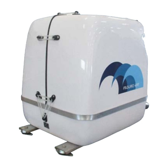
- Page 1 User and maintenance manual TYPE: MARINE GENERATORS MODEL: PAGURO P4MY - 5.5 MY YEAR OF CONSTRUCTION: 2022 Mod. PAGURO P4MY - 5.5 MY • Date: 13.05.2022_Rev: 0.0...
- Page 2 Revisions table CHAPTER DESCRIPTION REVISION DATE Warnings 13.05.2022 Technical specifications 13.05.2022 Operating conditions 13.05.2022 Operator 13.05.2022 Transport and handling 13.05.2022 Installation of the machine 13.05.2022 Installation errors 13.05.2022 Start and stop procedure 13.05.2022 Remote control pane 13.05.2022 General safety information 13.05.2022 Maintenance 13.05.2022...
- Page 3 Index WARNINGS Premise Introduction Purpose and contents of the User and Maintenance Manual General warnings Terminology used in the User and Maintenance Manual Obligation to keep the User and Maintenance Manual safe Manufacturer Details Technical Assistance General safety notes Warranty General safety warnings Operator instruction Work area...
-
Page 4: Table Of Contents
3.4 Categories of operators authorized to work and intervene on the machine 6.1 Sea inlet 3.4.1 Installers 6.2 Waterline 3.4.2 Ordinary maintainers 6.3 Exhaust line 3.4.3 Extraordinary maintainers 3.5 Exposure to hazards and risks from materials 7. START AND STOP PROCEDURE 3.6 Operators training 7 Start and stop procedure 7.1 Checks to be carried out before starting... - Page 5 Warnings PREMISE 10.5 Maintenance procedures This User and Maintenance Manual of the Marine Diesel Generator mod. Paguro 4 MY / 5.5 MY contains the 10.5.1 Replacing the sea water pump impeller instructions that allow the operator to use the machine to the best of its operational capabilities and provides all 10.5.2 Cleaning the sea inlet filter necessary information and instructions to operate in observance of the Machinery Directive 2006/42/EC.
- Page 6 TERMINOLOGY USED IN THE USER AND MAINTENANCE MANUAL OBLIGATION TO KEEP THE USER AND MAINTENANCE MANUAL SAFE. – WORK AREA: The operating area is defined as the area for the installation of the machine. You must keep this manual and all attached documents in an easily accessible place, near the machine, - INSTALLATION: Installation is defined as the mechanical and plant integration of the machine on the boat.
- Page 7 Warranty ADDITIONAL WARNINGS The company TE S.r.l. guarantees the machine according to the terms and times provided on the sales contract. At this point in the User’s and Maintenance Manual it is useful to provide a list of general safety requirements for the The warranty does not cover wear parts such as brass, gaskets, etc.
- Page 8 Operation principle EXPLOSIVE ATMOSPHERE The operation of the machine, for the generation of energy, develops through the following phases: This machine and its devices are made in standard version and can therefore not be installed and used in premises 1. The fuel arrives at the endothermic engine where, by means of the combustion process, it is transformed into where the concentration of dust may exceed acceptable limits and create potentially explosive atmospheres.
- Page 9 MACHINE SPECIFICATIONS 1. Technical specifications DESCRIPTION U.M. PAGURO 4 MY PAGURO 5.5 MY Engine rotation speed 3,100 3,100 1.1 “CE” IDENTIFICATION PLATE The picture below illustrates the identification plate of the machine. Continuous electrical power 50 Hz It is attached to the machine’s outer guard and shows: Single phase output voltage - Manufacturer identification data;...
- Page 10 Below is the Machine with a basic description of the main units and components installed. 1.3 COPYRIGHT WARNING! All rights are reserved under the “INTERNATIONAL COPYRIGHT CONVENTIONS”, it is forbidden to reproduce any part of this manual in any form, without the express written permission of the Manufacturer TE S.r.l.
- Page 11 2.4 LIGHTING 2 Operating conditions The machine, once installed, must have sufficient natural light to ensure adequate visibility to the operator during maintenance. It is the task of the operator to equip the boat with suitable artificial lighting systems such as to ensure adequate lighting on the machine in case of maintenance work.
- Page 12 2.6 NOISE POWER EMISSION NOTE: The external anti-vibration supports already have holes for securing the machine to the boat. In addition, in order to attenuate the vibrations transmitted to the boat and consequently to reduce the sound level The Paguro generator has been designed and manufactured to significantly reduce the sound power level. In particular, further, it is recommended to install, under the machine, a wooden platform, which in turn should be installed on soft the machine adopts a soundproofing capsule to limit the emission of the noise generated by the internal endothermic anti-vibration supports.
-
Page 13: Categories Of Operators Authorized To Work And Intervene On The Machine
3.4.2 Ordinary maintainers 3 Operator They are trained and authorized technicians for ordinary maintenance, each for its (mechanical or electrical) skills: – mechanical maintenance workers: they are technical workers, trained and authorized to perform the maintenance of mechanical parts and fluidic liquid/gaseous systems. –... -
Page 14: Transport And Handling
4 Transport and handling 4.1 GENERAL NOTIONS The lifting, handling, transport of the machine must be assigned exclusively to operators skilled in those types of operations (slingers, crane operators, forklift operators, signallers). Operators must also be: - aware of the kind of loads that require lifting, the operations that need to be carried out and the procedures set forth in the User and Maintenance Manual. -
Page 15: Lifting And Handling With Forklift
4.2.2 Lifting and handling with forklift This type of handling is used to move the packed machine. WARNING! Always check where the forks rest under the box. To lift with a forklift, follow these steps: a) Insert the fork of the truck under the wooden box, taking care that they protrude from the opposite side. b) Lift the machine slightly and make sure that the load is in balance. -
Page 16: Unpacking
4.3 UNPACKING Once the machine has been unloaded from the means of transport, unpack it according to the following procedure: 1. Remove the optional cardboard box strapping (if equipped); 2. Remove the top cover of the wooden case using a hammer with a nail puller; 3. -
Page 17: Storage
5. Installation of the machine 4.5 STORAGE If there is a possibility that the machine will not be installed immediately, but has to be warehoused for a prolonged period of time, the storage must take place in a sheltered environment, with a degree of protection appropriate for the installed components. -
Page 18: Ventilation
5.4 EXTERNAL CONNECTIONS The location of the external connections is shown in the images below. The various connections must be made with suitable diameters (as indicated in Chap. 1 “TECHNICAL SPECIFICATIONS”) not only to avoid leaks and drips, but also to avoid unnecessary openings of the silencing capsule with If possible, position the machine away from any splashes of water and vapours. -
Page 19: Exhaust System Installation (On Request)
5.5 EXHAUST SYSTEM INSTALLATION (on request) The VTE S.r.l. warranty does not cover errors and inaccuracies in the installation of the exhaust line. VTE S.r.l. recommends the installation of the exhaust line of the “in-line” mufflers. The machine is supplied as standard with an exhaust, combustion gas and sea water terminal, on which an overtemperature switch is installed. -
Page 20: On-Board System With Space Shortage
5.5.3 On-board system with long exhaust line In the case of a very long exhaust pipe, it is recommended to use an exhaust system with a double anti-siphon muffler (see picture below). Due to the large amount of water in the exhaust line, the second anti-siphon muffler protects the machine from water return. -
Page 21: Installation Of The Cooling System
DIESEL SUPPLY AND RETURN DIAGRAM WITH MACHINE LEVEL IN RELATION TO TANK ≥ 70 CM (example) NOTE: The injection pump of the machine is a self-draining pump. This means that if the engine is shut down due to lack of fuel, after filling the tank, there is no need to purge the air manually, but it is sufficient to operate the lever of the pre-fuel pump. -
Page 22: Anti-Siphon Valve
5.7.1 Anti-siphon valve 5.7.2 Sea water inlet (on request) If the generator is installed below or near the waterline (refer to external anti-vibration dampers), an anti-siphon valve VTE S.r.l. recommends the “grid” type of sea inlet. must be installed between the cooling water supply and the water-cooled drain terminal. This inlet must be installed in the NON-DYNAMIC direction, i.e., façades of grids in the stern direction and round-off The anti-siphon valve prevents water from entering the engine through the water pump when the engine is installed side closed toward the bow, on the hull, under the waterline, considering all possible inclinations of the boat. -
Page 23: External Installation - Main Voltage Connection
The electrical connection of the generator with the inverter requires: a. Plugging the multipolar connector of the inverter into the corresponding socket installed on the generator; Multipolar socket on-board the machine b. Inserting the three-phase cable into the inverter input socket (1); c. -
Page 24: Remote Control Connection
5.8.4 Remote control connection The standard supply is a remote control panel with a 15 m cable, so that it can be used in any part of the boat provided it is protected from weather. The cable has a quick connector on both sides. To connect the remote control to the machine, insert the multipolar socket on the remote panel to the corresponding socket on the lower guard of the machine. -
Page 25: Preliminary Checks
5.9 PRELIMINARY CHECKS 6 Installation errors After installation, and before commissioning the generator, a series of checks must be carried out in order to prevent errors and accidents: – Check that the machine has not been damaged during transport and installation; –... -
Page 26: Start And Stop Procedure
Regardless of the quantity, which must obviously be correct, the colour of the oil indicates whether water is present: 7 Start and stop procedure • Transparent yellow indicates that the oil is new. • Black indicates that the oil has turned for a few hours. •... -
Page 27: Running-In Of The Machine
WARNING! Repeated attempts to start without cranking result in water filling in the exhaust line, After the first 20 hours of operation of the machine, check the maintenance table (par. 10.2.7) for the resulting in engine damage. correct maintenance operations to be carried out. This is caused by the sea water pump which circulates the cooling water, but since the burned gases are not present, the water fills the exhaust line until it enters the engine. -
Page 28: Remote Control Panel
An icon will also appear on the display to help you quickly identify any alarm generated by the machine. 8 Remote control panel 2. START Button to start the machine. Press and hold the button until the machine starts. 8.1 CONTROL PANEL DESCRIPTION The machine is supplied with the remote-control panel. -
Page 29: Electrical Connections (8 Wires Blue Cable / Control Panel)
8.3 ELECTRICAL CONNECTIONS (8 WIRES BLUE CABLE / CONTROL PANEL) 9 General safety informations The table below shows the electrical connections between the machine, the 8-wire cable and the control panel. Before carrying out maintenance operations on the machine, read the instructions in this chapter carefully. 9.1 PREVENTING ELECTRIC SHOCK •... -
Page 30: Accidental Power On
9.4 ACCIDENTAL POWER ON 10 Maintenance • Accidental start can cause injury or death! • Disconnect the battery cables before operating the machine. Disconnect the negative first and reconnect it last after you have done the work. • Make sure operators are away from the machine before switching on. The term “MAINTENANCE”... -
Page 31: Ordinary Maintenance
10.2.3 Functional checks on safety devices 2. Access to the machine is allowed only to authorized personnel; 3. Do not modify or tamper with the machine structure without a written statement to the company VTE S.r.l.; The primary task of the ordinary maintenance technician is to check the efficiency of the safety devices after every 4. -
Page 32: General Advice
10.2.5 General advice OPERATIONS TO BE CARRIED OUT DAILY To carry out the maintenance operations safely: • Check the engine oil level. If the level does not exceed the minimum level, top up; – respect the timescale for scheduled maintenance as stated in the User and Maintenance Manual (preventive and •... -
Page 33: Extraordinary Maintenance
OPERATIONS TO BE PERFORMED EVERY 500 HOURS The ordinary maintenance technician must update every copy of the User and Maintenance Manual in the customer’s • Clean the heat exchanger tube bundle. possession; the changes must be highlighted and marked in writing on every copy of the User and Maintenance •... - Page 34 Mod. PAGURO P4MY - 5.5 MY • Date: 13.05.2022_Rev: 0.0 Mod. PAGURO P4MY - 5.5 MY • Date: 13.05.2022_Rev: 0.0...
-
Page 35: Maintenance Procedures
10.5 MAINTENANCE PROCEDURES 10.5.2 Cleaning the sea inlet filter The following paragraph provides specific procedures for servicing the machine. The sea inlet filter is one of the fundamental components of the machine cooling system. Check the condition of the Maintenance operations must be carried out with the machine in maintenance state by authorized technical personnel. filter frequently. -
Page 36: Replacing Engine Oil
10.5.5 Replacing engine oil Carry out the engine oil change according to the following procedure: 1. Start the engine and bring it up to operating temperature; 2. Stop the engine; 3. Remove oil dipstick 1 to allow the engine oil to drain more easily; 4. -
Page 37: Cleaning The Air Purification Element
Cleaning of the air purification element Cleaning of the air purification element 10.5.7 Cleaning the air purification element 10.5.8 Machine cleaning To clean the air-purifying element correctly and safely, follow the steps below: Perform a thorough cleaning of the machine. 1. -
Page 38: Maintenance Of The Endothermic Engine
11 Types of risks and safety pictograms included WARNING! Sulphuric acid in lead batteries can cause burns on the skin and damage clothing. Wear protective gloves before working on the batteries. 11.1 RISKS OF A MECHANICAL NATURE A 5 AMP fuse on the remote control protects the battery charging circuit. The lack of illumination in the This paragraph describes the mechanical risks that can arise during installation or maintenance operations on the remote control may be due to the blown fuse. -
Page 39: Design And Physical Features Of Safety Guards
11.5 OTHER NATURE RISKS OR RESIDUAL RISKS 11.5.1 Risk of fire The machine uses diesel fuel and engine oil, which can cause fire if it comes into contact with parts that are generating or subjected to extreme temperatures. The safety of the machine against fire is closely linked to maintenance operations and to the observance of the timing. - Page 40 RECTANGULAR SHAPE REMOTE CONTROL PANEL (PREVIOUS VERSION) R&D Department ROUND SHAPE REMOTE CONTROL 3B 3C 8A,4C CONTROL PANEL (CURRENT VERSION) STARTING BATTERY Date: Page MANUAL Microtec - Inverter 4 kVA 15/06/2020 1 of 2 8 WIRES BLUE CABLE BETWEEN Written by: L. Micheli Last revision:1.00 (15-06-2020) SOLENOID THE REMOTE CONTROL PANEL...
- Page 41 SHEET OF MAINTENANCE INTERVENTIONS All repair, recording, replacement and overhaul work must be recorded in the “SHEET OF MAINTENANCE INTERVENTIONS”. The authorized maintainer must record any changes. DATE GROUP WORK PERFORMED TECHNICIAN SIGNATURE Notes: Mod. PAGURO P4MY - 5.5 MY • Date: 13.05.2022_Rev: 0.0 Mod.
- Page 42 Mod. PAGURO P4MY - 5.5 MY • Date: 13.05.2022_Rev: 0.0 Mod. PAGURO P4MY - 5.5 MY • Date: 13.05.2022_Rev: 0.0...
-
Page 43: Mod. Paguro P4My - 5.5 My • Date: 13.05.2022_Rev
VTE Srl Via Luciano Lama, 5 33059 Fiumicello Villa Vicentina (UD) - Italy Tel. +39 0431 96488 Fax +39 0431 970634 www.volpitecno.com Mod. PAGURO P4MY - 5.5 MY • Date: 13.05.2022_Rev: 0.0...
Need help?
Do you have a question about the PAGURO P4MY 5.5 MY and is the answer not in the manual?
Questions and answers