
Summary of Contents for Erskine Attachments SC72
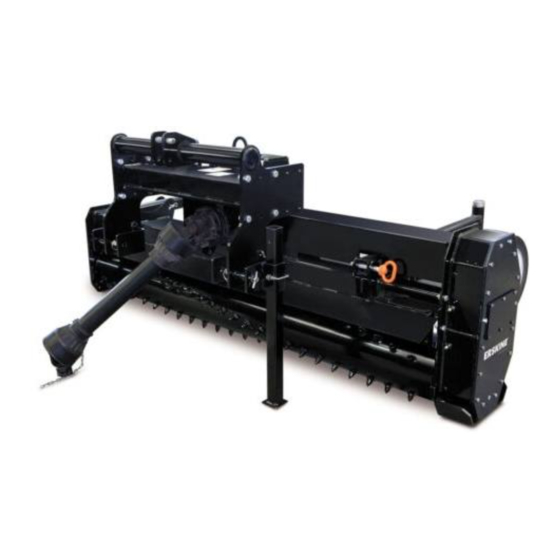
- Page 1 Soil Conditioner Skid Steer Loaders Operator’s Manual Set-Up Assembly Maintenance Parts Information Read this Manual Before Use...
-
Page 2: Table Of Contents
Serial Number………….. YOUR ATTACHMENT DEALER ADDRESS: PHONE: CONTACT: NOTE: Erskine Attachments LLC reserves the right to make improvements in design or changes in specifications at any time without notice and without incurring any obligations to install them on units previously sold. -
Page 3: Safety
Indicates potentially Erskine Attachments LLC cannot anticipate every hazardous situation which, if not avoided, possible circumstance that might involve potential will result in death or serious injury. - Page 4 Keep all shields, guards, and covers in place. injury. • Do not modify equipment or add attachments that • Avoid the hazard by relieving the are not approved by Erskine Attachments LLC. pressure before disconnecting hydraulic lines. • Use adequate safety warning lights and devices as required by local regulations.
-
Page 5: Serial Number/Decal Location
SERIAL NUMBER AND SAFETY DECAL LOCATIONS Serial Number Location: It is important to refer to the serial number of your attachment when making repairs or ordering parts. Early or later models (identification made by serial number) may use different parts, or it may be necessary to use different procedures in doing a specific operation. - Page 6 Safety Decals Locations: The locations of the safety decals are shown. If these decals are missing, damaged, or Small Brand Decal painted over they must be replaced. Call Location: On each endplate Erskine Attachments LLC (218-435-4045) for Quantity: 2 replacement decals.
-
Page 7: User's Mounting Instructions
USER’S MOUNTING INSTRUCTIONS After the initial set-up assembly is completed (see page 16 of this manual), use the following procedure to mount the attachment to the loader for user operation. Coupler wedges or pins must extend through the holes in the attachment mounting plate. - Page 8 USER’S MOUNTING INSTRUCTIONS 7. Connect the hydraulic quick couplers from the attachment to the loader. IMPORTANT: Wipe the ends of the hydraulic quick couplers (both lead and loader) with a rag remove possible contamination. Contamination cause hydraulic components to fail and is not covered under warranty.
-
Page 9: Operating Instructions
OPERATING INSTRUCTIONS Getting Started 1. Before using the attachment, survey the entire area carefully to make sure that there aren’t any obstructions that may interfere with operation or damage the attachment. IMPORTANT: Usually, clearing an area of rocks is the final operation, except for areas that have abundant rocks. - Page 10 OPERATING INSTRUCTIONS Adjusting Working Depth The tilling depth should always be 1 to 2 inches in order to loosen the soil. Rock jamming could occur if the rotor depth is too great. Deeper tilling should only be done in an area that is rock free. The attachment working depth can be changed by adjusting the loader tilt and lift, hitch pin, or the wheel supports.
- Page 11 OPERATING INSTRUCTIONS Adjusting the Rubber Shield The rubber shield can be adjusted up to 2”, to better suit the type of soil you are conditioning. To adjust the rubber shields, loosen all shield bolts, move the rubber shield to the desired location and retighten the bolts.
-
Page 12: Routine Maintenance
ROUTINE MAINTENANCE Lower the attachment to rest flat on the ground, shut down the engine, relieve the hydraulic pressure to the attachment, wait for all motion to stop, and set park brake before leaving the operator’s seat to perform service of any kind. It is the operator’s responsibility to make daily inspections of the loader and attachment for damage, loose bolts, fluid leaks, or anything else that could cause a potential service or safety problem. - Page 13 ROUTINE MAINTENANCE Grease the (2) lower mounting plate pivot bushings [C] after every 8 hours of operation. Grease the lift pivot pin [D] after every 8 hours of operation. NOTE: Pivot pin [D] found on floating mount models only. Grease the rotor bearing [E] after every 80 hours of operation.
-
Page 14: Set-Up Assembly
SET-UP ASSEMBLY Caster Wheel Installation The soil conditioner is shipped with the caster wheels arms pinned backwards on the unit. After cutting the banding, it will be necessary to remove the pins on the attachment. The caster wheels and arms need to be flipped and bolted onto the attachment using the hardware provided. - Page 15 SET-UP ASSEMBLY 4. Route the wiring harness back along the tube lines on the loader arms and fasten with cable ties. 5. Open the rear door and pull the excess wiring into the engine compartment. 6. Raise the operator cab (see loader’s operator’s manual for the correct procedure).
-
Page 16: Parts Information
SOIL CONDITIONER RIGID FRAME PARTS INFORMATION ITEM PART NO. DESCRIPTION STOCK NO. 319151 FRAME MAIN HYD 72" W/A FRAME MAIN HYD 84” W/A 319150 FRAME MAIN HYD 96” W/A 340400 319153 SIDE PLATE W/A 420007 SKID SHOE W/A 420008 ARM WHEEL W/A 317055 CASTER W/A 319193... - Page 17 SOIL CONDITIONER RIGID FRAME PARTS INFORMATION...
- Page 18 SOIL CONDITIONER FLOAT FRAME PARTS INFORMATION ITEM PART NO. DESCRIPTION STOCK NO. 319151 FRAME MAIN HYD 72" W/A FRAME MAIN HYD 84” W/A 319150 FRAME MAIN HYD 96” W/A 340400 319153 SIDE PLATE W/A 420007 SKID SHOE W/A 420008 ARM WHEEL W/A 317055 CASTER W/A 319193...
- Page 19 SOIL CONDITIONER FLOAT FRAME PARTS INFORMATION...
- Page 20 SOIL CONDITIONER HYDRAULIC PARTS INFORMATION ITEM PART NO. DESCRIPTION STOCK NO. 319002 ROTOR 72" W/A ROTOR 84” W/A 319003 ROTOR 96” W/A 340401 319085 BRG 1-1/2 F-BOLT FLG B-TYPE 319124 WASHER SHAFT END PAINTED 319125 WASHER BOLT LOCK PAINTED 319118 MOTOR HYD 19 CID 6K SERIES 201527 ADPT STR 16MB-12MJ...
- Page 21 SOIL CONDITIONER HYDRAULIC PARTS INFORMATION Manual Angling Hydraulic Angling (viewed from back side)
- Page 22 WIRE HARNESS PARTS INFORMATION REF. PART NO. DESCRIPTION QTY. COMPLETE HARNESS – generic (shown)……………………1 315128 PISTOL GRIP – handle assembly w/ harness…………………1 315110 LOADER HARNESS – assembly………………………………..1 315126 RECEPTACLE BRACKET – loader harness…………………...1 202489 BLOWER HARNESS – assembly………………………………..1 315127 Optional Harnesses (not shown): 14-PIN UNIVERSAL –...
-
Page 23: General Specifications
GENERAL SPECIFICATIONS Model SC72 SC84 SC96 72” 84” 96” Rotor Width Angling Manual 25° Manual 25° Manual 25° Hydraulic Angling Optional Optional Optional Wheels/Tires 18 x 8.50 Polyurethane 18 x 8.50 Polyurethane 18 x 8.50 Polyurethane Teeth Carbide Carbide Carbide... -
Page 24: Bolt Torque Information
BOLT TORQUE INFORMATION... -
Page 25: Troubleshooting
TROUBLESHOOTING Problem Possible Cause Solution Poor soil conditioning Hydraulic leak or restricted flow Check hydraulic lines and motor for performance leaks or pinch points. Insufficient hydraulic flow from Check loader relief and flow rate by loader performing a flow rate test. Loose motor bolts Check bolts on motor for proper torque. -
Page 26: Notes
NOTES ____________________________________________________ ____________________________________________________ ____________________________________________________ ____________________________________________________ ____________________________________________________ ____________________________________________________ ____________________________________________________ ____________________________________________________ ____________________________________________________ ____________________________________________________ ____________________________________________________ ____________________________________________________ ____________________________________________________ ____________________________________________________ ____________________________________________________ ____________________________________________________ ____________________________________________________ ____________________________________________________ ____________________________________________________ ____________________________________________________ ____________________________________________________ ____________________________________________________ ____________________________________________________ ____________________________________________________ ____________________________________________________ ____________________________________________________ ____________________________________________________ ____________________________________________________ ____________________________________________________ ____________________________________________________ ____________________________________________________ ____________________________________________________ ____________________________________________________... -
Page 27: Warranty
Erskine Attachments LLC to improve its products whenever it is possible and practical to do so. Erskine Attachments LLC reserves the right to make changes and or add improvements at any time without incurring any obligation to make such changes or add such improvements to products previously sold. - Page 28 P/N 300658 Date Printed: 4/24/2020 Printed in U.S.A. Erskine Attachments LLC...
Need help?
Do you have a question about the SC72 and is the answer not in the manual?
Questions and answers