Advertisement
Quick Links
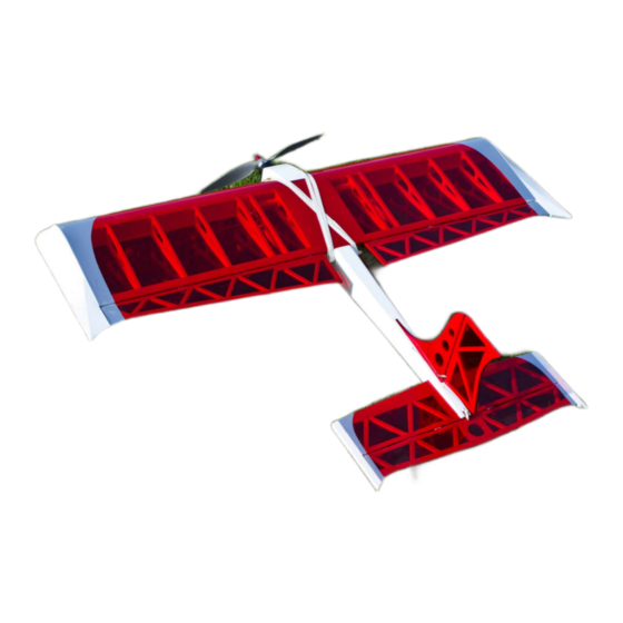
Micro Fusion II Instruction
FEATURES
Precision Laser Cut Parts
Lightweight Strong Airframe
Excellent Low Speed Stability
Comprehensive Instruction Manual
High Quality Balsa Ply and Depron parts
Excellent Precise Handling Characteristics
High Quality Comprehensive Hardware Pack
Manual
0
Advertisement

Related Manuals for Evolution Micro Fusion II


Summary of Contents for Evolution Micro Fusion II
- Page 1 Micro Fusion II Instruction Manual FEATURES Precision Laser Cut Parts Lightweight Strong Airframe Excellent Low Speed Stability Comprehensive Instruction Manual High Quality Balsa Ply and Depron parts Excellent Precise Handling Characteristics High Quality Comprehensive Hardware Pack...
- Page 2 (Glow Version)! The Evolution Fusion has been designed to meet the needs of the Fun Fly competition pilot in an attractive package. We hope that you have as much fun building and flying it as we have had developing it! Building Recommendations Check all parts from the box to ensure that they are present;...
-
Page 3: Hardware Pack
Micro Fusion Part List Wood Pack Description Sheet Size Quantity Metric Imperial Webbing Sheet 1.5 x 75 x 457mm 1/16 x 3 x 18” Leading and Trailing Edge Sheet 1.5 x 75 x 915mm 1/16 x 3 x 36” Leading Edge 4.5 x 18 x 915mm 3/16 x 3/4 x36”... - Page 4 Laser Cut Parts...
- Page 5 Part No. Description Sheet Material Left and Right Fuselage Sides (2) 3mm (1/8”) Balsa UC centre spacer Plate 3mm (1/8”) Balsa Tail Plane Tips (2) 4.5mm (3/16) Balsa Elevator Tips (2) 4.5mm (3/16) Balsa Aileron Outer Tips (2) 4.5mm (3/16) Balsa Rudder Leading Edge 4.5mm (3/16) Balsa Rudder Bottom Frame...
- Page 6 Fusion Parts List Piano Wire U/C Front Leg 12 swg Rear Leg 12 swg Supports 12 swg Tail Skid 16 swg Description Quantity Undercarriage Front Leg Undercarriage Rear Leg Undercarriage Support Tail Skid...
-
Page 7: Building Instructions
Building Instructions Fin and Rudder Take the six parts that form the Fin and Rudder (Parts 12, 11, 6, 8, 7 and 9), trial fit before gluing together using Cyano or white wood glue. With the supplied strip of 4.5 x 6mm (3/16” x 1/4”) cut to length to form the centre ribbing pieces. - Page 8 Wit h a sharp knife cut the slots for four hinges 10mm in from either end and evenly spaced, ensure that the Elevator sits centrally on the Tail Plane. Cut 3/8” (10mm) strips from the supplied Mylar hinge material and insert into the hinge slots, 50% in the Elevator and 50% into the Tail Plane.
- Page 9 Glue the excess triangular fillet to the underside of F2 and dry fit between the Fuselage sides, ensure that F1 fits in the 3mm (1/8”) recess left at the front. If you are building the electric version carefully drill holes at the top and the bottom of the former to allow air to enter the Fuselage for cooling.
- Page 10 If you are building the electric version take the battery hatch floor (Part 33) and place the tab under the ply U/C mount and mark the ends as shown below. Draw line here Remove the section of triangular balsa and plank with the 3mm (1/8”) from this point to the back of the Fuselage.
- Page 11 Adjust to suit before gluing in the skid with epoxy. Do not glue the Fin in at this stage. Ensure that the Tail Plane can fit into the Fuselage slot and the Fin slot without fouling. Wing and Aileron We recommend building the entire wing with Aliphatic Wood Glue. It is generally fast setting and can be sanded at the same rate as balsa.
- Page 12 As you install W2 take a piece of paper and roll into a tube to carry the servo wires to the centre section, this is optional, but we Find this makes the installation look tidier. These need to be inserted as work proceeds as it is impossible to insert after all the ribs are in place.
- Page 13 Cut the 1.5mm x 6mm x 915mm (1/16” x ¼” x 36”) capping strips to length and glue in place. Ensure good bond with the leading and trailing edge sheeting to prevent these pieces moving independently as this will cause problems when sanding, repeat to the bottom of the wing. Take the servo mounting plates (Parts) from the birch ply and cut holes to suit your chosen servos.
- Page 14 Where the tip extends past the trailing edge of the wing make a fillet with scrap 1/8” (3mm) balsa as shown in the right hand picture above. Shape the leading edge roughly with a razor Plane before Finishing with sand paper as shown in the diagram on page 11, continually checking the fit to the Fuselage.
- Page 15 Covering Before covering seat the wing, Tail Plane and Fin and make sure that all fit. Make any alterations as necessary with Fine sandpaper and a block. Finally sand all parts to provide a smooth, blemish free surface ready for covering. !!! Warning. Ensure that you are wearing an appropriate mask for sanding balsa and are in well ventilated area, we recommend sanding in free air (outside).!!! This is your chance to express yourself;...
- Page 16 Cyano. Ensure the Cyano penetrates through the cotton. Final Assembly If you have any queries about the Final assembly then please contact us at support@evolution-models.com where we will be happy to discuss your problem and send you a photo to two to illustrate our solution. Wing Take the fully covered wing and ailerons, glue the hinges 50% into the aileron using a thin Cyano and ensure that it penetrates into the slots both top and bottom.
- Page 17 With the supplied pushrods rods make a ‘Z’ bend using ‘Z’ bend pliers or needle nose pliers as shown in the diagram below. Push the ‘Z ‘ bend through the horn and the servo adaptor as per the diagram below. Make sure all the joints are secure;...
- Page 18 Glue the Tail Plane into position, apply the glue inside the slot, top and bottom, and with help carefully open the slot while inserting the Tail Plane and release the Fuselage to clamp back down. Only apply slight pressure so as not to break the rear of the Fuselage. When inserting the Tail Plane be careful not to get glue onto the covering.
- Page 19 Make up the closed loop systems to the Elevator and Rudder as shown below. Ensure the crimps hold the wire tightly, place a drop of Cyano to make sure the wires cannot move. Motor Mount Mount the motor using the recommended motor mount ensuring that it is securely attached to the firewall, do not use screws, only use lock nuts, bolts and washers suitable for this application.
- Page 20 Rudder – 65mm Left and Right measured at the top These control throws will provide docile flight characteristics, suitable for test flying. Once confident in the models performance increase the rates. At Evolution we fly our display models with the following settings on the transmitter high rate settings: Ailerons - 45mm Up and Down measured at the tip Elevator –...
- Page 21 Evolution Models do not have any control over the Final assembly of the model or material used for Final assembly. No liability shall be assumed for damage resulting from the use of this product. By the act of using the Final assembled product the user accepts all resulting liability.
Need help?
Do you have a question about the Micro Fusion II and is the answer not in the manual?
Questions and answers