
Summary of Contents for STRIKE-ARC SACUT40
- Page 1 USER MANUAL DC INVERTER PLASMA CUTTER MODELS: SACUT40 PLEASE READ THE USER MANUAL BEFORE USE.
- Page 2 INTRODUCTION The Air Plasma Cutter can be used for a wide range of cutting applications: stainless steel, alloy steel, copper, aluminum, and all other color metal materials. You will need a suitable Compressor to operate the CUT40 Air Plasma Cutter. Clean dry air supply is required: 350KPA/3.5 BAR - 550KPA /5.5BAR, to the machine.
-
Page 3: Electric Shock Can Kill
They must be emptied and properly cleaned first. Blow out with clean air as fumes can ignite * Do not cut in areas containing explosive dust or vapors. * Do not cut pressurized containers of any kind. * Wear oil-free clothing and protective gear such as leather gloves, heavy shirt, cuff less pants, high tight shoes, and a cap. -
Page 4: Excessive Noise
After disconnecting the power supply, there is still SIGNIFICANT DC VOLTAGE in the inverter power sources. If you must open the unit for any reason, Turn Off unit, disconnect input power, and check input Voltage. Capacitors store electricity, ensure that they are near zero (0) volts before touching any parts. -
Page 5: Technical Data
continuous as long as power is supplied to the electrode and the plasma stays in contact with the metal that is being cut. The cutter nozzle has a second set of channels. These channels release a constant flow of shielding gas around the cutting area. -
Page 6: Installation
INSTALLATION Unpacking Unpack all items and verify that all items have been received according to the packing list enclosed. Operating Environment Make sure working area is well ventilated. The unit is cooled by an flow fan which provides airflow through the back panel over the electronics and out the machine cover vents. -
Page 7: Operation
Unscrew the electrode. Install the new electrode, and tip. Replace worn parts, where necessary. Install and hand tighten the shield cup until it is seated on the torch head. If resistance is felt when installing the cup, check the threads and parts before proceeding. OPERATION Process Turn the Power Switch to the ON position. -
Page 8: Maintenance
the workpiece as you cut. Dross occurs when the operating procedure and technique is less than optimal. It will require practice and experience to obtain cuts without dross. Although less than optimal cuts will contain dross, it is relatively easy to remove by breaking it off using pliers or chipping off with a chisel or scraping or grinding the finished cut as needed and is generally only a minor inconvenience. -
Page 9: Troubleshooting
TROUBLESHOOTING PROBLEM CAUSE SO LUTI O N Turn Power Switch to the On Power Switch Off Position Another indication of this is a Air supply is Power Switch Off greener flame. compromised Check air supply. Attach to work piece or to Work piece Ground steel table with work piece Clamp not attached... - Page 10 Inspect and repair or replace Worn torch parts worn parts Arc stops while cutting Connect W ork piece Ground Work piece ground Clamp to work- piece or cable disconnected steel table. Cutting speed too fast Slow travel speed Torch tilted too much Adjust tilt.
-
Page 11: Parts Listing
PARTS LISTING No. PART No. PART HANDLE 19. MAIN TRANSFORMER HANDLE SEAT 20. RADIATOR 1 METAL COVER 21. THERMOSTAT 22. RECTIFIER TRANSITOR 23. BAKELITE DIGITAL DISPLAY 24. UPRIGHT POTENTIALMETER 25. IGBT POTENTIALMETER KNOB 26. RADIATOR 2 FAST CONNECTOR 27. RECTIFIER BRIDGE 10. -
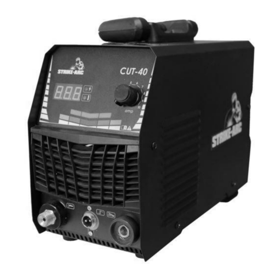
Page 12: Panel Instruction
PANEL INSTRUCTION Model: SACUT40 1. POWER INDICATOR LIGHT 2. CURRENT METER 3. OVER-LOAD (HEAT) INDICATOR LIGHT 4. CURRENT ADJUSTER 5. TORCH AVIATION SOCKET OUTLET 6. NEGATIVE OUTPUT (TORCH) 7. POSITIVE OUTLET (EARTH CLAMP) - Page 14 NAMEPLATE SYMBOL AND GRAPHIC MEANING Symbol Meanings Single phase static frequency changer-transformer-rectifier Static External Characteristics is dropping characteristic Welding Power source symbol of Fit welding operation II Category Protection Symbol Manual arc welding with coated electrode Single phase power source/ three phase power source / 3~ DC (direct current)
- Page 15 Contact your dealer for repair/warranty claims. Packing List Name Main Body Cutting Torch Pressure Reducing Value Ground Wire Manual Strike-Arc products are exclusively manufactured for and distributed by Agrinet(Pty) Ltd. Private Bag x165,Centurion,0046 T: +27(0) 12 657 2222 enquiries@agrinet.co.za Made in PRC...
Need help?
Do you have a question about the SACUT40 and is the answer not in the manual?
Questions and answers