
Related Manuals for amber connect Amber Power C400

Summary of Contents for amber connect Amber Power C400
- Page 1 Quick Start Guide APC400 Amber Power C400 LTE Vehicle Terminal Install Your device Download Amber Connect Activate the device...
-
Page 2: Product Overview
Product overview Position tracking GPS & LBS positioning • • Real-time location query Anti-theft Ignition detection • • Power/Fuel cut-off SOS emergency call • Power supply disconnection alert Geo-fence alert • Towing alert • Vibration alert • Configurable peripherals Vehicle door status alert •... -
Page 3: Product Setup
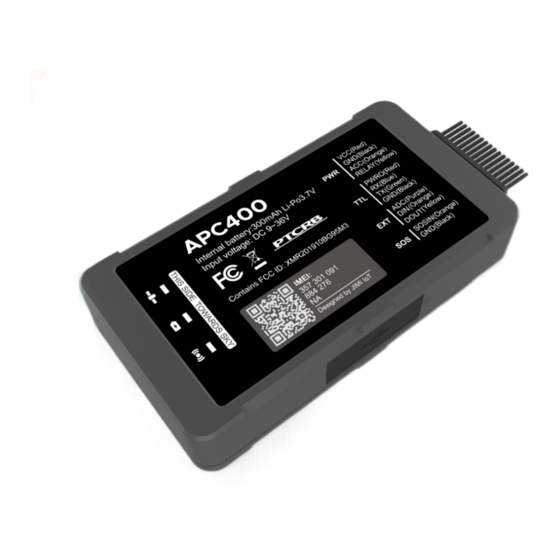
9V to 36V DC Operating Voltage -30°C to +85°C for storage Operating Temperature Transmit Protocol Product setup Insert SIM Remove the soft plug on one side of the device and insert the SIM card into the card slot. Power on & off Toggle the power switch besides the SIM slot to power on or off the device. - Page 4 Wireless Network & SIM Card Status (Green} Behaviour Meaning SIM card not recognized On for 0.5s and off for 0.5s Registered but no inbound On for 2s and off for 4s acknowledgement Network connected On for 0.1 s and off for 4s No signal received or no SIM card detected Interfaces DC 9 to 36v input...
-
Page 5: Power Connection
Wiring indication Power connection The standard power supply ranges from 9V to 36VDC. During installation, negative side should connect to the ground. Do not connect with other ground wires simultaneously. -
Page 6: Relay Wiring
Ignition wire ACC line (orange) connects to vehicle's ACC, detecting ignition. Be sure to check if it's a real ignition wire Le. power does not disappear after starting the engine. Relay wiring Relay's white line (85) connects to the positive side of battery (12V) while the yellow line (86) connects to the device relay control (yellow line on the power cord). -
Page 7: Installation Recommendation
Installation recommendation • The device should face up to the sky. • Metal thermal barrier or heating layer of the windshield affects the signal. Troubleshooting Type Check the APN and IP settings. Unable to connect to tracking platform Check whether the data service of SIM card is enabled. -
Page 8: Warranty Instructions
Warranty instructions 1. The warranty is valid only when the warranty card is property completed, and upon presentation of the proof of purchase consisting of original invoice indicating the date of purchase, model and serial No. of the product. We reserve the right to refuse warranty if this information has been removed or changed after the original purchase of the product from the dealer.
Need help?
Do you have a question about the Amber Power C400 and is the answer not in the manual?
Questions and answers