Table of Contents
Advertisement
Quick Links
DFB-CWDM-M Module User's Manual
Caution: The user must read this manual before operating the DFB module unit.
Operations other than those described in this manual may result in personal
injury and damage to the unit.
Note that any attempt to open or fix the equipment without prior approval by
Optilab, LLC voids the warranty.
Ver. 1.1
th
October 30
, 2019
Advertisement
Table of Contents

Related Manuals for OPTILAB DFB-CWDM-M

Summary of Contents for OPTILAB DFB-CWDM-M
- Page 1 DFB-CWDM-M Module User’s Manual Caution: The user must read this manual before operating the DFB module unit. Operations other than those described in this manual may result in personal injury and damage to the unit. Note that any attempt to open or fix the equipment without prior approval by Optilab, LLC voids the warranty.
- Page 2 Copyright © 2019 by Optilab, LLC. All rights reserved. This document is copyrighted property of Optilab, LLC. It may not be used in whole or in part for manufacture, sale, or design of items without the written permission of Optilab, LLC.
-
Page 3: Table Of Contents
2.6 RS232 C OMMAND 3. TROUBLESHOOTING 4. SERVICE AND SUPPORT 4.1 W ARRANTY 4.2 S ERVICE AND ALIBRATION 4.3 C ARE OF IBER OPTIC ONNECTORS Optilab, LLC 600 E. Camelback Road, Phoenix, AZ 85012 Phone: (602) 343-1496, Fax: (602) 343-1489, Email: sales@oequest.com... -
Page 4: General Information
DFB-CWDM-M Module User’s Manual Page 1 of 7 1. General Information 1.1 Introduction This manual contains information on the installation and operation of the Optilab DFB-CWDM-M module unit. 1.2 Product Overview The Optilab DFB-CWDM-M series products are CWDM Distributed Feedback (DFB) laser sources in module housing. -
Page 5: User Safety
Page 2 of 7 1.4 User Safety 1. The DFB-CWDM-M module unit emits high intensity light from the optical output receptacle. Avoid direct exposure to skin and eyes. 2. The equipment case is fully certified for EMS protection. The user should never open the equipment case;... -
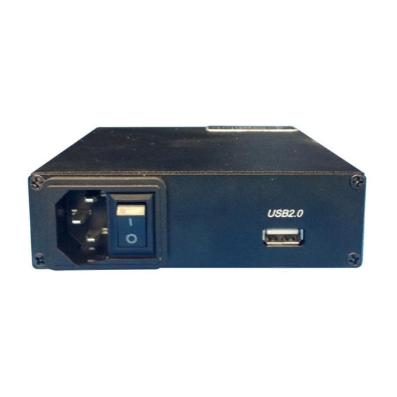
Page 6: Panel Diagrams And Controls
DFB-CWDM-M Module User’s Manual Page 3 of 7 2.3 Panel Diagrams and Controls DFB-CWDM-M Module Panels EATURE UNCTION The AC power socket is the input for the AC power source. A three-pin standard power cord should be used to connect ... -
Page 7: Operation Instructions
If you have a DFB-CWDM-M unit with additional software control, please refer to the following below for the software connection option. Using a USB cable, connect the DFB-CWDM-M to a PC using the following connection diagram and serial port settings: Optilab, LLC 600 E. -
Page 8: Rs232 Command Set
C: Optical output connector damaged. S: Measure optical output power with power meter and compare with readout on Main Display. Return to Optilab for repair if the difference is high (>4 dB) and cannot be corrected by cleaning or replacing the optical connectors. Always apply dust cover plugs to unused optical receptacles to prevent the damage of internal optical connectors. -
Page 9: Service And Support
4. Service and Support 4.1 Warranty Optilab, LLC guarantees its DFB-CWDM-M module unit to be free of defects for 1 year from the date of shipment. The guarantee does not cover any damages resulting from the misuse or improper handling of the equipment, or any incidental or consequential loss. -
Page 10: Care Of Fiber-Optic Connectors
DFB-CWDM-M Module User’s Manual Page 7 of 7 4.3 Care of Fiber-optic Connectors Damage to optical connectors account for more than 70 percent of equipment performance degradation. To avoid such damage, the user should use only industrial grade 99% pure isopropyl alcohol and follow the procedures below to keep the connectors, adaptors and receptacles clean.
Need help?
Do you have a question about the DFB-CWDM-M and is the answer not in the manual?
Questions and answers