Advertisement
Quick Links
Overview:
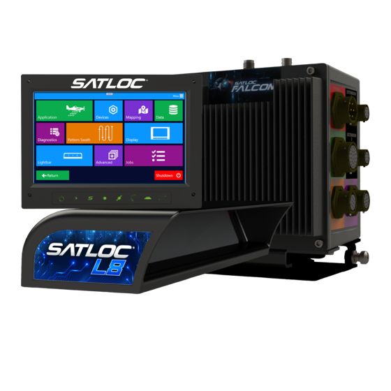
This installation guide lists all the parts in the
Falcon GPS System kit and provides instructions on installing the Falcon
GPS System components, associated cables, and switches.
Read this manual thoroughly before beginning the installation.
If you have any questions, contact your local dealer or Satloc Customer Service.
Satloc Falcon Installation Guide
1
875-3004-000 Rev A2
Advertisement

Summary of Contents for TRANSLAND Satloc Falcon
- Page 1 Falcon GPS System kit and provides instructions on installing the Falcon GPS System components, associated cables, and switches. Read this manual thoroughly before beginning the installation. If you have any questions, contact your local dealer or Satloc Customer Service. Satloc Falcon Installation Guide 875-3004-000 Rev A2...
- Page 2 Documentation Feedback Satloc, a division of Transland, is committed to the quality and continuous improvement of our products and services. We encourage and appreciate any feedback regarding this guide and any of our products by writing to the following email address: Sales@Translandllc.com.
-
Page 3: Safety Information
Do not obstruct the view of, or access to, other instruments or the flying visibility of the operator. Do not allow anyone to operate without instruction. For trouble-free operation and maintenance of your Falcon system, avoid using Falcon in extreme environmental conditions (40-140°F is recommended operating temperature range). Satloc Falcon Installation Guide 875-3004-000 Rev A2... -
Page 4: Table Of Contents
TABLE OF CONTENTS Safety Information: Chapter 1: Getting Started Chapter 2: Mounting the Components Chapter 3: Connecting the CPU Appnendix A: A21 GPS Antenna Mounting Dimensions Satloc Falcon Installation Guide 875-3004-000 Rev A2... -
Page 5: Chapter 1: Getting Started
Chapter 1: Getting Started Parts Lists Component Weights Planning the Installation Satloc Falcon Installation Guide 875-3004-000 Rev A2... - Page 6 Kit, Falcon, slide mount hardware 710-2001-000 Kit, Falcon control components 710-2007-000 PCA, IMU, Falcon, Calibrated* 725-2050-000 Kit, IMU mounting* 710-2004-000 Manual, Installation Guide, Satloc Falcon, (this manual) 875-3004-000 *Only included in the Falcon Pro CPU Kit. Satloc Falcon Installation Guide 875-3004-000 Rev A2...
- Page 7 Table 1-4: Optional - Falcon Second GPS Upgrade Kit (PN 900-4104-000) Component Part Number Novatel 7600 receiver 750-6000-000 A21, L1 GNSS, LBAND antenna 804-3036-000# Cable, RF, MCX(M)-TNC(F) 050-2516-000 Cable, RF-X, TNC(M)-TNC(M), 5M 052-0005-000# Kit, Novatel 7600 mounting components 710-2005-000 Satloc Falcon Installation Guide 875-3004-000 Rev A2...
- Page 8 Avoid high-temperature exposure (for example, exhaust manifold) when routing cables. • Do not allow anyone to operate without instruction. In planning the installation locations, see Chapter 3, “Connecting the CPU,” for a visual overview of how the components are connected. Satloc Falcon Installation Guide 875-3004-000 Rev A2...
-
Page 9: Chapter 2: Mounting The Components
Chapter 2: Mounting the Components Mounting the CPU Mounting the Touchscreen Installing the Cockpit Switches Mounting the Lightbar Mounting the A21 GPS Antenna Mounting the Monopole ADS-B In Antenna Satloc Falcon Installation Guide 875-3004-000 Rev A2... - Page 10 (Optional, not included in kits. Dealer may request a template.) Mounting Layout Template for Falcon/IF3 Rack Mount (Optional, not included in kits. 601-1317-000 Dealer may request a template.) Mounting Layout Template for Falcon/IF3 Horizontal Mount Satloc Falcon Installation Guide 875-3004-000 Rev A2...
- Page 11 (Ref A) to the CPU. v) Use references Bd, Be, and Bf to attach vibration isolators (Ref Bc) to approved structure. vi) Use references Ba and Bb to attach vibration mounts to horizontal mounting brackets (Ref A). Satloc Falcon Installation Guide 875-3004-000 Rev A2...
- Page 12 Mark the fastener hole locations of the four fastener locations. There are four holes at #16 drill bit (0.177”). iv) Drill holes being careful not to cause damage. v) Use locally sourced hardware to attach the CPU to approved structure. Satloc Falcon Installation Guide 875-3004-000 Rev A2...
- Page 13 Do not drill holes in screen cover. This will void the warranty. Table 2-2: Falcon Touchscreen Mount Parts PART NUMBER DESCRIPTION PHOTOGRAPH 9” Display 806-4403-000 050-2201-000 Cable, cockpit Cable, display encoder 050-2528-000 Cable, display IO 050-2529-000 050-2525-000 Cable kit, display to panel USB Satloc Falcon Installation Guide 875-3004-000 Rev A2...
- Page 14 There is an optional dash mount bracket (PN 601-1321-000) that can be used with the touchscreen display. This is for NOTE: Air Tractor aircraft. Satloc Falcon Installation Guide 875-3004-000 Rev A2...
- Page 15 USB port PN 050-2525-000. With the cable, connect the port to the back of the display. Figure 2-3: Install Image of Optional USB Port Satloc Falcon Installation Guide 875-3004-000 Rev A2...
- Page 16 2 (of 10) Nut, #10-32 *80570 2 (of 10) Washer, #10-32 *81219 050-2205-000 L8 Lightbar cable for Falcon *Part of Hardware Kit A drill and 1/4" drill bit are required for this installation. P/N 710-2003-000 Satloc Falcon Installation Guide 875-3004-000 Rev A2...
- Page 17 Plus or minus 10 Do not hit any wires or degrees. Examples shown below. hydraulics while drilling. Check both sides of the aircraft before drilling. Figure 2-4: Tilting Angles of L8 Lightbar Satloc Falcon Installation Guide 875-3004-000 Rev A2...
- Page 18 Exploded View Step Two Step One REF C and E REF B, C and D Step Five REF B, G and H Figure 2-5: Exploded View of L8 Lightbar Mount Satloc Falcon Installation Guide 875-3004-000 Rev A2...
- Page 19 Satloc recommends flush mounting the antenna along the aircraft’s centerline, with an unobstructed view of the sky NOTE: and horizon. Table 2-6: A21 GPS Antenna Mount Parts PART NUMBER DESCRIPTION PHOTOGRAPH 804-3036-000# A21, L1 GNSS, LBAND antenna 052-0005-000# Cable, RF-X, TNC(M)-TNC(M), Satloc Falcon Installation Guide 875-3004-000 Rev A2...
- Page 20 Use four #8-32 thread screws Connect cable PN 052-0005- to secure the antenna (PN 000# to antenna PN 804-3036- to the aircraft’s 000#. 804-3036-000#) surface. Black RTV silicone can be used to seal around the antenna base. Satloc Falcon Installation Guide 875-3004-000 Rev A2...
- Page 21 The following tools are needed to mount the antenna: • Drill, 7/16” drill bit • Marker pen Table 2-7: ADS-B In Monopole Antenna Mount Parts PART NUMBER DESCRIPTION PHOTOGRAPH Antenna, monopole ADSB-IN 804-4000-000 050-2522-000 Cable, ADS-B In Satloc Falcon Installation Guide 875-3004-000 Rev A2...
- Page 22 ADS-B In Antenna Using a 7/16” drill bit, carefully Use the hardware with PN 804- drill the hole for the antenna 4000-000 to secure antenna to connector. aircraft surface. Connect cable PN 052-2522-000 to antenna. Satloc Falcon Installation Guide 875-3004-000 Rev A2...
-
Page 23: Chapter 3: Connecting The Cpu
Chapter 3: Connecting the CPU Warnings Cables to Connect the CPU Cables to Connect the Touchscreen Display Connections Diagram Connecting Cables Satloc Falcon Installation Guide 875-3004-000 Rev A2... - Page 24 Do not connect Spray On/Off leads to a flow system if it contains live voltage. Table 3-1: Cables to Connect the Falcon CPU PART NUMBER DESCRIPTION PHOTOGRAPH Cable, power / relay for Falcon CPU 050-2200-000 050-2201-000 Cable, cockpit 050-2202-000 Cable, GPIO Cable, comports (COMM) 050-2203-000 Satloc Falcon Installation Guide 875-3004-000 Rev A2...
- Page 25 1 (If 050-2206-000 Cable, extension L7 - Falcon connecting to L7 Lightbar) 050-2522-000 Cable, ADS-B In 052-0005-000# Cable, Antenna - TNC(M)-TNC(M) 5M 804-4001-000 Antenna, WIFI, dual band 050-2521-000 Optional Cable, extension for WIFI antenna Satloc Falcon Installation Guide 875-3004-000 Rev A2...
- Page 26 Table 3-2: Cables to Connect the Falcon Touchscreen PART NUMBER DESCRIPTION PHOTOGRAPH Cable kit, display to panel USB 050-2525-000 Cable, display encoder 050-2528-000 050-2529-000 Cable, display IO 050-2536-000 Cable, display audio out Satloc Falcon Installation Guide 875-3004-000 Rev A2...
- Page 27 Each cable fits into its appropriate port. Line up a connector with its matching pins and gently insert and turn. Tighten the connectors until they lock into place. Figure 3-1: Connections to Front of Falcon Figure 3-2: Install Image of Connections to Front of Falcon Satloc Falcon Installation Guide 875-3004-000 Rev A2...
- Page 28 Do not coil the cables. This will introduce noise in the system. • Avoid high-temperature exposure (for example, exhaust manifold) when routing cables. • Cross the antenna cable (if necessary) at 90° to any other cable (prevents cross-interference). Satloc Falcon Installation Guide 875-3004-000 Rev A2...
- Page 29 Relay C2 wire - route to something like a smoker or camera that needs to be turned on and off, this is optional Satloc Falcon Installation Guide 875-3004-000 Rev A2...
- Page 30 Satloc suggests to use optional switch PN 075-0035-000. The GPS and flow control systems operate off of different NOTE: voltage signals. Therefore, there is a possibility that feedback will occur with only one switch. Also, as a switch ages, there might be degradation in the signal. Satloc Falcon Installation Guide 875-3004-000 Rev A2...
- Page 31 Connect the Conxall connector of PN 050-2205-000 or PN 050-2206-000 into one of the Falcon’s extension ports. Then, connect the metal Bendix of PN 050-2205-000 or PN 050-2206-000 to the matching connector on the back of the lightbar. Satloc Falcon Installation Guide 875-3004-000 Rev A2...
- Page 32 VDC. Connect the Conxall connector of PN 050-2200-000 into the Falcon’s CPU power port. There is an ON/OFF switch (PN 424-0003-000) included in the Satloc Falcon kit. This switch contains a built-in 12 A (max) circuit breaker that prevents voltage spikes and reverse polarity from damaging the system.
- Page 33 2. P4 CAN COM 4 3. P2 AgLaser COM 2 - connects to AgLaser directly Wires COM 12 Volt Out 12 Volt GND OUT1 GND OUT1 Signal IN1 Signal IO1 Signal RX3/FLW-MTR IN TX3/FLW-MTR 5V Satloc Falcon Installation Guide 875-3004-000 Rev A2...
- Page 34 The ADS-B In cable (PN 050-2522-000) connects on the top of the Falcon’s CPU to the ADS-B In port. The other end of the cable connects to the ADS-B In monopole antenna. PN 050-2522-000 PN 804-4000-000 Figure 3-10: Connect ADS-B In cable to ADS-B In antenna and Falcon CPU Satloc Falcon Installation Guide 875-3004-000 Rev A2...
-
Page 35: Appnendix A: A21 Gps Antenna Mounting Dimensions
APPENDIX A: A21 GPS ANTENNA MOUNTING DIMENSIONS The “Antenna Mounting Dimensions” drawing is not a template. Instead, it gives the mounting dimensions. When mounting the antenna, measure off the center, where zero initiates. Satloc Falcon Installation Guide 875-3004-000 Rev A2... - Page 36 Technical Support To find an authorized dealer near you, visit www.satloc.com. Satloc support@satloc.com Call or Text 833-4-Satloc (833) 472-8562 www.satloc.com 1206 Hatton Rd. Wichita Falls, TX 76302...
Need help?
Do you have a question about the Satloc Falcon and is the answer not in the manual?
Questions and answers