Table of Contents
Advertisement
Quick Links
Advertisement
Table of Contents

Related Manuals for TKH SVS-VISTEK CoaXPress EoSens 10CXP2

Summary of Contents for TKH SVS-VISTEK CoaXPress EoSens 10CXP2
- Page 1 EoSens® 10CXP2 User Guide...
-
Page 2: Table Of Contents
Content Before you start About this manual 1.1.1 Tips, remarks, and notes 1.1.2 Registered trademarks 1.1.3 Conformity and use 1.1.4 Supplements Warranty and non-warranty clause Support Introduction Intended use Scope of delivery Optional accessories System requirements The camera Camera description Operating temperature Active cooling Interfaces of the camera... - Page 3 Spectral response 5.5.1 Monochrome and color...
-
Page 4: Before You Start
Before you start About this manual This manual contains helpful information to install and operate the described cam- era. It has been produced with care. Nevertheless, information might be erroneous or incomplete. SVS-Vistek GmbH cannot be held responsible for any problems resulting from incomplete or erroneous information. -
Page 5: Supplements
idential area is likely to cause harmful interference in which case the user will have to correct the interference at its own expense. NOTICE You are herewith cautioned that any changes or modifications not expressly approved in this description could void your authority to operate this equipment. 制... -
Page 6: Warranty And Non-Warranty Clause
NOTICE SVS-Vistek GmbH customers using or selling these products for use in such applic- ations do so at their own risk and agree to fully indemnify SVS-Vistek GmbH for any damages resulting from such improper use or sale. Warranty and non-warranty clause NOTICE The camera does not contain serviceable parts. -
Page 7: Introduction
Introduction Intended use The camera EoSens® 10CXP2 belongs to the product class of so-called high-speed machine vision (MV) cameras that are integrated into test or measurement systems. High-speed MV cameras are designed to capture images with high frame rate for various purposes in an industrial or scientific environment to deliver image data for further analysis. -
Page 8: System Requirements
Power supply If you do not use power over CXP, you need an external power supply unit, e.g.: NTCAM132X (12 V/2.5 A) with 12 pin Hirose connector (HR10A-10P-12S(73) and 5 m cable NTCAM132XIO (12 V/2.5 A) with 12 pin Hirose connector (HR10A-10P-12S (73) and 5 m cable plus additional strobe out line System requirements The PC or image processing system that is connected with the camera must be... -
Page 9: The Camera
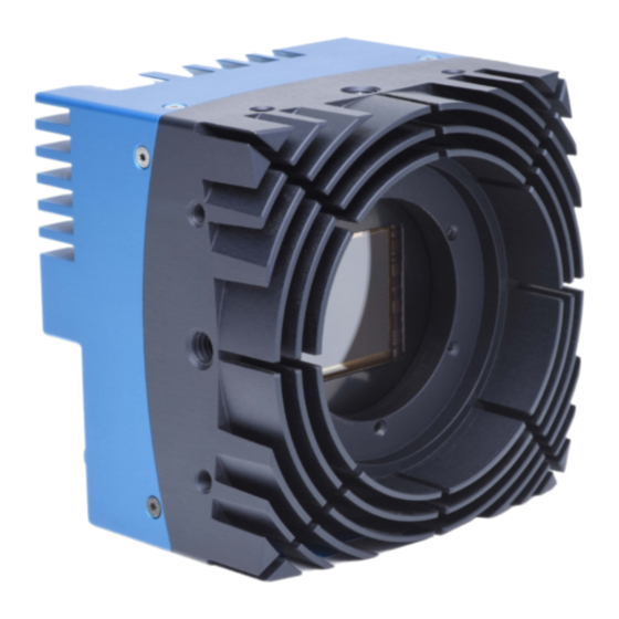
The camera Camera description All cameras of the EoSens CXP family are CoaXPress compliant. The high-speed CMOS cameras come with a 10 Megapixel sensor of 4,608 x 2,176 px (H x V). They are widely configurable and scalable, and are available in monochrome and color (Bayer Filter). -
Page 10: Operating Temperature
Operating temperature If the camera is mounted on mechanical parts, the heat generated during operation will be dissipated by the attached fan, the cooling fins at the rear of the camera, and the mechanical parts. NOTICE The camera body temperature must not exceed the values specified in the technical data (see "Technical data"... -
Page 11: Interfaces Of The Camera
Interfaces of the camera Fig.: 3-1: Interfaces of the camera EoSens® 10CXP2 1 Status LED to verify the operating status of the camera 2 Four CoaXPress µBNC connectors to connect the camera with a CoaXPress compliant frame grabber. The ∆- marked line can supply the camera with power via power over coax (PoC). -
Page 12: Status Led
Status LED The multi-color status LED indicates camera and connection states. LED State Indication No power Solid orange System is booting Slow pulse red Powered, but nothing connected (not applicable if PoC is used) Fast flash alternate Connection detection in progress, PoC active green/orange Fast flash orange Connection detection in progress, PoC not in use... -
Page 13: First Steps
First steps Connecting a frame grabber The transmission speed of the camera can either be set to 3.125, 5, 6.25, 10, or 12.5 Gb/s. The possible cable length depends on the cable type used, its quality, and the selected transmission speed. The following table provides examples. These values will only be reached if the signal quality meets the requirements of the CXP2.0 specification. -
Page 14: Connecting An External Power Supply Or I/O Signals
The possible connector combinations are shown in the table below. No. of con- Connector combination nections 2 1+2 (link) 4 1+2+3+4 (link) INFO All connections are hot-pluggable. Connecting an external power supply or I/O signals If you prefer an external 12 - 24V DC power supply (min. 18 W), connect it with the 12-pin connector at the rear of the camera. - Page 15 Internally connected with: pin 4 pin 8 pin 6 pin 10 connected with pin 3 + 5 Fig.: 4-1: Connecting input and output signals with the internal circuit All inputs accept 3.3 V LVTTL signals. They are also 5 V TTL compatible. All inputs can also accept signals with 12 ...
-
Page 16: Connecting Camera And Image Processing System
Connecting camera and image processing system NOTICE To make use of the full performance, all cables, connectors and the frame grabber must be CoaXPress V2.0 compliant. INFO If a CXP V1.1 frame grabber is used, only speeds up to CXP-6 (6.25 Gb/s) can be achieved. -
Page 17: Cleaning Sensor And Lens
INFO The camera has NOT to be configured by the host to start operation. The power-up profile will deliver all necessary values. Serial number and firmware version are provided in the non-volatile memory of the camera. Use the GenICam feature “DeviceSerialNumber” to read the serial number and the firmware revision. - Page 18 2. Select the CTI file that corresponds to the frame grabber board. If unsure, con- sult the Device Manager. 3. To add a CTI file that is not in the list, select Add another CTI file and navigate to the file. 4.
-
Page 19: Technical Data
Technical data Camera specifications Frame rate (8 bit) 478 fps Shutter speed 4 µs – 1 s Shutter time (steps) 1 µs Max. Jitter via CXP ±4 ns Trigger Quantum efficiency >62% @ 500 nm Interfaces CoaXPress 1.x @ 3.125 Gb/s CoaXPress 1.x @ 6.25 Gb/s CoaXPress 2.x @ 10 Gb/s CoaXPress 2.x @ 12.5 Gb/s... -
Page 20: Sensor Specifications
Sensor specifications Sensor type CMOS global shutter Image sensor size 20.74 mm x 9.79 mm Resolution 10 Megapixel Active pixels 4,608 x 2,176 px ROI min 128 x 32 px Pixel depth 8 bit / 12 bit Pixel size 4.5 x 4.5 μm Dynamic range up to 68 dB (12 bit Gain 2) Full well charge >30 ke- (12 bit Gain 0) -
Page 21: Camera Dimensions
Camera dimensions INFO All dimensions in Millimeters. Fig.: 5-1: Rear view Fig.: 5-2: Side view without adapter 5 Technical data... - Page 22 92.9 46.5 Fig.: 5-3: Side view with F-mount adapter Spectral response 5.5.1 Monochrome and color Fig.: 5-4: Spectral response - monochrome and color 5 Technical data...
- Page 23 SVS-Vistek GmbH Ferdinand-Porsche-Str. 3 82205 Gilching Phone: +49 8105 3987-60 https://www.svs-vistek.com info@svs-vistek.com © 11-2022 This document and the product(s) described are subject to change without further notice.
Need help?
Do you have a question about the SVS-VISTEK CoaXPress EoSens 10CXP2 and is the answer not in the manual?
Questions and answers