
Subscribe to Our Youtube Channel
Related Manuals for Woodward EGCP-1

Summary of Contents for Woodward EGCP-1
- Page 1 26059 EGCP-1 Engine Generator Control Package 8406-020, 12 Vdc 8406-021, 24 Vdc Operation (End User) Manual Manual 26059...
- Page 2 Woodward Governor Company reserves the right to update any portion of this publication at any time. Information provided by Woodward Governor Company is believed to be correct and reliable. However, no responsibility is assumed by Woodward Governor Company unless otherwise expressly undertaken.
-
Page 3: Table Of Contents
Manual 26059 EGCP-1 Engine Generator Control Package Contents CHAPTER 1. GENERAL INFORMATION................1 Introduction..........................1 Declaration of Incorporation ....................1 Control Options ........................1 Control Part Numbers......................1 CHAPTER 2. ELECTROSTATIC DISCHARGE AWARENESS..........3 CHAPTER 3. CONTROL OVERVIEW ................5 Introduction..........................5 Operator Interface .......................7 CHAPTER 4. SOFTWARE OVERVIEW................9 Introduction..........................9... - Page 4 Replacement Parts ......................123 How to Contact Woodward ..................... 123 Additional Aftermarket Product Support Services ............124 Technical Assistance ...................... 126 APPENDIX A. EGCP-1 SETPOINT WORKSHEET ............127 Configuration Menu......................127 Shutdown and Alarms Menu ................... 128 Engine Control Menu ...................... 134 Synchronizer Menu ......................
- Page 5 Manual 26059 EGCP-1 Engine Generator Control Package 4-29 Direct (Export) Process Action .................35 4-30 Indirect (Import Power) Process Action............35 4-31 Direct (Import/Export) Process Action ..............36 4-32 EGCP-1 Control Dip Switch ................36 4-33 Breaker Logic and Contactor Logic ..............37 4-34 Generator High/Low Voltage Alarms..............40 4-35 Generator Over/Under Frequency..............41...
- Page 6 EGCP-1 Engine Generator Control Package Manual 26059 Woodward...
-
Page 7: Chapter 1. General Information
Woodward Governor Company, is applied solely as a component to be incorporated into an engine prime mover system. Woodward Governor declares that this controlling device complies with the requirements of EN50081-2 and EN50082-2 when put into service per the installation and operating instructions outlined in the product manual. - Page 8 EGCP-1 Engine Generator Control Package Manual 26059 Woodward...
-
Page 9: Chapter 2. Electrostatic Discharge Awareness
Manual 26059 EGCP-1 Engine Generator Control Package Chapter 2 Electrostatic Discharge Awareness All electronic equipment is static-sensitive, some components more than others. To protect these components from static damage, you must take special precautions to minimize or eliminate electrostatic discharges. - Page 10 EGCP-1 Engine Generator Control Package Manual 26059 Woodward...
-
Page 11: Chapter 3. Control Overview
EGCP-1 Engine Generator Control Package Chapter 3 Control Overview Introduction The EGCP-1 is a microprocessor based complete generator load control and engine management package designed for use with a Woodward speed control and a separate voltage regulator. The control's functions include: Engine Control •... - Page 12 • KVAR droop for manual VAR control. Automatic Generator Sequencing • Automatically starts additional EGCP-1 equipped generators when load exceeds a user specified percentage of the rated load of the operating machines. • Provides controlled unloads for engines when the load is low enough that the remaining engines will not exceed a user specified percentage of the rated load.
-
Page 13: Operator Interface
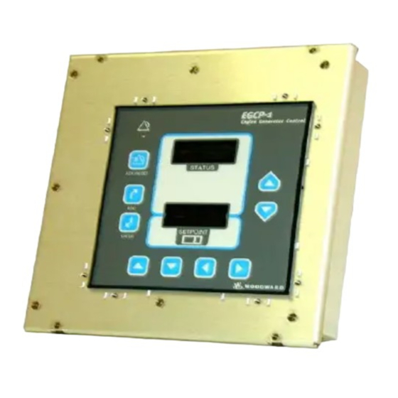
EGCP-1 Engine Generator Control Package Operator Interface The EGCP-1 Operator Interface is designed for simplicity and redundancy of function in all operating modes. The backlit LCD screens with contrast adjustment are used to display various operating and status information to the operator, as well as for reading tuning setpoints. - Page 14 EGCP-1 Engine Generator Control Package Manual 26059 Up Key Down Key Left Key Right Key Moves Cursor Moves Cursor Moves Cursor M oves Cursor Increments Val. Decrements Val. R ig h t H a n d T e a rd ro p K e y s...
-
Page 15: Chapter 4 Software Overview
Software Overview Introduction The software used in the EGCP-1 uses state machine logic to operate in all modes. State machine logic relies upon discrete inputs, and specific operating conditions to trigger a sequence of operations. The state machine logic use the... - Page 16 EGCP-1 Engine Generator Control Package Manual 26059 Program Navigation Status Menus Action Screen Power Up Control Overview Status Overview: Escape Button Depressed Control Overview Engine Overview Gen. Overview Gen. Phases I/O Status Alarms Sequencing Load Control Monitor Up Button Depressed...
-
Page 17: Status Screens
EGCP-1 Engine Generator Control Package Status Screens When the EGCP-1 is initially powered up, it will default to the Control Overview Screen. Here is what the Screen looks like. The Control Overview Screen can also be accessed while in any other status screen by pressing the UP teardrop key twice. -
Page 18: Control Overview Screen-Set For Loss Of Mains Detection
Pressing the ESCAPE KEY will take the display from the Control Overview menu to the Status Menu. The Status Menu is the menu which gives an overview of all the status menus available in the EGCP-1. This is what the Status Menu looks like:... -
Page 19: Status Menu (Cont.)
Manual 26059 EGCP-1 Engine Generator Control Package There are a total of nine status menus. Use the down arrow key on the face of the EGCP-1 to access the other three status menus. I/O STATUS SEQUENCING LOAD CONTROL MON Figure 4-4. Status Menu (cont.) Use the up and down arrow keys to move the blinking cursor to the desired status menu that will be viewed. -
Page 20: Generator Overview (Voltage Line To Line)
EGCP-1 Engine Generator Control Package Manual 26059 0.00 0.00 0.00 Hz: 00.0 KW: 00.0 PF: 1.00 LAGGING (LOAD CONT. STATUS) Figure 4-6. Generator Overview (Voltage Line to Line) The Unit network address is displayed here. Aφ, Bφ, Cφ: Three phase readings for the generator. -
Page 21: Synchroscope
The voltage differential in percent between the generator and the bus or mains it is paralleling to. Mains/Bus: The active PT input being monitored by the EGCP-1. Dead Bus: Indicates if the PT input (mains or bus) being measured is dead. -
Page 22: Example Of Two Typical Fault Listings
EGCP-1 Engine Generator Control Package Manual 26059 U n a c k F a u lts: 2 F a u lts L is tin g : O V E R S P E E D 3 -2 6 1 1 :1 5... -
Page 23: I/O Status
Manual 26059 EGCP-1 Engine Generator Control Package Discrete I/O 1 2 3 4 5 6 7 8 9 0 1 2 3 4 5 6 I I I - - - - - Volt Bias: Speed Bias: Figure 4-11. I/O Status Discrete Inputs 1 through 16. -
Page 24: Sequencing Menu
EGCP-1 Engine Generator Control Package Manual 26059 Unit: Oper: Prty: Master Unit: 1 Next On: All Next Off: Figure 4-12. Sequencing Menu Unit:Network Address of all units in Auto on the network. Oper:Units in auto, and on the network with their breakers closed and on load. -
Page 25: Tuning Screens
The final Status Screen is Load Control Monitor. This screen does not appear on the display unless the level 4 security code is entered at the EGCP-1. The Load Control Monitor is used for accessing technical information about the EGCP-1. -
Page 26: Example 1
EGCP-1 Engine Generator Control Package Manual 26059 Various Security codes access different portions of the tuning screens, depending on the level of security code used. Like the status screens, the up and down keys are used to move the blinking cursor to the tuning menu that the user wants to enter. -
Page 27: Example 2
Manual 26059 EGCP-1 Engine Generator Control Package Status Menus Listing C O N T R O L O V E R V IE W E N G IN E O V E R V IE W G E N O V E R V IE W... -
Page 28: Example 3
EGCP-1 Engine Generator Control Package Manual 26059 I/O Status Menu D is c re te I /O O O - - - V o lt B ia s : S p e e d B ia s : Escapes I/O Status Menu... -
Page 29: Example 4
Manual 26059 EGCP-1 Engine Generator Control Package C O N T R O L O V E R V IE W E N G IN E O V E R V IE W G E N O V E R V IE W... -
Page 30: Example 5
EGCP-1 Engine Generator Control Package Manual 26059 Setpoint Menu Security Code **** Selects Security Code Setpoint Changes Security Code Setpoint Value Enters Setpoint Value Figure 4-19 . Example 5 Woodward... -
Page 31: Example 6
Manual 26059 EGCP-1 Engine Generator Control Package Setpoint Menu Security Code Security Code Setpoint Entered Cursor Moves Back to Security Code Item Security Code Moves to next item in Configuration Menu Escapes back to Setpoint Menu List Figure 4-20. Example 6... -
Page 32: Example 7
EGCP-1 Engine Generator Control Package Manual 26059 Setpoint Menu Configuration Shutdowns and Alarms Scrolls through Main Setpoint Menu Enters Desired Menu Item Scrolls through Selected Menu item Overspeed 1980 Figure 4-21 . Example 7 Woodward... -
Page 33: Example 8
Manual 26059 EGCP-1 Engine Generator Control Package Overspeed 1980 Selects Value for Tuning Tunes Value Overspeed 1650 Enters New Value Escapes and Resets Value to Original Value Figure 4-22. Example 8 Woodward... -
Page 34: Example 9
EGCP-1 Engine Generator Control Package Manual 26059 Shutdown and Alarm Menu Overspeed Item committed Overspeed 1650 Figure 4-23. Example 9 Shutdown and Alarm Menu Overspeed Item committed Overspeed 1650 Navigates through other menu items Steps Back to Main Setpoint Menu Lis... -
Page 35: Example 11
Manual 26059 EGCP-1 Engine Generator Control Package Shutdowns/Alarms Real Load Control Steps to Status Menu Screen C O N T R O L O V E R V IE W E N G IN E O V E R V IE W... -
Page 36: Alarm Navigation Example 1
EGCP-1 Engine Generator Control Package Manual 26059 Active Alarm or Shutdown Removes Audible Alarm Output (If Used) Enter Operator or Higher Security Code Enter Alarm/Event Status Menu Unack Faults: 2 Faults Listing: OVERSPEED 3-26 11:15 1700 LOW OIL PRESSURE 3-26 11:14 Figure 4-26. -
Page 37: Alarm Navigation Example 2
Manual 26059 EGCP-1 Engine Generator Control Package Selects Alarm List Items Acknowledges and Commits Selected Item Clears Selected Item A maximum of 8 alarms can be logged at any time. The most recent alarms will appear higher in the Alarm Status Menu than older Alarms. - Page 38 EGCP-1 Engine Generator Control Package Manual 26059 • All Items in Configuration Menu must be Committed before engine operation will be allowed. Uncommitted items will have an asterisk (*) next to them on the screen. All Generator Parameters (KVA, KW, KVAR, Frequency, and Rated Voltage) must be within ranges as defined by the following: •...
-
Page 39: Ac Power Triangle
Manual 26059 EGCP-1 Engine Generator Control Package • Defines typical operating frequency of generator. Rated Speed (numeric) • Synchronous Speed Of Generator Set. • Used in Speed Calculation to determine “sample” period for MPU input. Rated KW (numeric) • Rated KW of Generator. - Page 40 • KW Limits, etc. Voltage Input (Wye L-N, Delta L-L) • Set for sensing/transformer used between generator and EGCP-1. • Defines which calculations will be used for KW, KVA, KVAR, etc. • Defines the expected input type for voltage levels in the setpoint menus.
-
Page 41: Direct (Export) Process Action
Manual 26059 EGCP-1 Engine Generator Control Package 20 mA export power speed bias 4 mA Figure 4-29. Direct (Export) Process Action 20 mA imported power speed bias 4 mA Figure 4-30. Indirect (Import Power) Process Action Woodward... -
Page 42: Direct (Import/Export) Process Action
Process Import/Export Hardware • EGCP-1 Control can take a 4–20 mA, or 1–5 Vdc input signal from a transducer. Input signal conditioning is selected by a dip switch on the back of the control, switch position 8, switch number 8. -
Page 43: Breaker Logic And Contactor Logic
Manual 26059 EGCP-1 Engine Generator Control Package Circuit Breaker Control (Breaker/Contactor) • Defines action of Generator and Mains closure command. • Breaker issues momentary breaker close signal, and a separate momentary breaker open signal independently. • Contactor issues continuous breaker close signal through the breaker close command relay output. - Page 44 EGCP-1 Engine Generator Control Package Manual 26059 • If multiple unit, auto starting, auto sequencing, load and VAR/PF sharing are available between all units in multiple. Unit displays system sequencing information on sequencing screen. Network Priority and Network Address setpoints are added to the configuration setpoint menu automatically. Unit must be in Auto mode to communicate over the inter-control network (RS-485).
- Page 45 Alarm can be set for Loss of Mains. • If Mains Frequency is above High Limit, Mains are not considered stable, and the EGCP-1 control will not issue a mains breaker closure command. Mains Frequency Low Limit (numeric) • Alarms when Mains Frequency drops below setpoint.
-
Page 46: Generator High/Low Voltage Alarms
EGCP-1 Engine Generator Control Package Manual 26059 Generator High Voltage Limit (Voltage Bias Cutout) Rated Generator Voltage Generator Low Voltage Limit (Voltage Bias Cutout) Figure 4-34. Generator High/Low Voltage Alarms Generator Volt High Limit (numeric) • Sets maximum allowable generator voltage level. -
Page 47: Generator Over/Under Frequency
Manual 26059 EGCP-1 Engine Generator Control Package Generator High Frequency Limit (Speed Bias Cutout) Synchronous Speed (50/60 Hz) Generator Low Frequency Limit (Speed Bias Cutout) Figure 4-35. Generator Over/Under Frequency Generator High/Low Frequency Limits • Even if the Alarm Setpoints for the High/Low Limits are Disabled, the Speed Bias will not allow adjustment beyond these limits. -
Page 48: Overcurrent Level-High Current, Short Duration
EGCP-1 Engine Generator Control Package Manual 26059 Per Phase amps Overcurrent Trip Zone overcurrent level 100% rated current time overcurrent delay Figure 4-36. Overcurrent Inverse Time Function amps Overcurrent Trip Zone overcurrent level time overcurrent delay Figure 4-37. Overcurrent Level—High Current, Short Duration... -
Page 49: Reverse Power
LOE alarm triggers. • Used to indicate loss of field excitation to the generator. Battery Volt High Limit (numeric) • Sensed DC voltage supply to EGCP-1. • Can be used to detect faulty charging circuit. Battery Voltage Low Limit (numeric) •... - Page 50 Engine rpm level where crank command is canceled. Crank Delay • Time between Engine Crank Attempts. Crank Repeats • Number of times EGCP-1 will attempt to re-start engine. Cranking attempts will equal the value of Crank Repeats +1. Crank Fail • Alarm Setpoint. •...
- Page 51 Normal operating mode. • Actively synchronizes and issues breaker closure command. • EGCP-1 control MUST be in RUN to operate as a dead bus closing device. • In multiple unit systems EGCP-1 control MUST have AUTO input active to enable breaker control.
-
Page 52: Typical Circuit Using Permissive Function And Run For Auto/Manual Synchronizing
Voltage Window (numeric) • Overall percentage of error allowed between generator and bus, or generator and mains. • EGCP-1 control will not issue a breaker closure if error is greater than voltage window. Gen Voltage High Bus or Mains Voltage 484.8 VAC 480 VAC 475.2 VAC... -
Page 53: Maximum Phase Window = 10 Degrees
• Maximum allowable phase angle deviation from phase matched condition. • EGCP-1 Control will not issue breaker closure if phase angle between generator and bus, or generator and mains exceeds this window. Must be within +/- 10 deg window for breaker closure Figure 4-42. - Page 54 EGCP-1 Engine Generator Control Package Manual 26059 Synchronizer Time Out • Sets time allowed for synchronization in seconds. • Begins timing when synchronizer activates. • Active for all gen and mains breaker open and close commands from EGCP- 1 control.
- Page 55 Load Level where Generator Breaker/Contactor open command will be issued when EGCP-1 control is off loading generator set. Load Droop • Percentage of KW droop used when EGCP-1 control is operating in a droop mode. Load Time • Time in Seconds for generator to load from unload trip level to base load level.
- Page 56 EGCP-1 Engine Generator Control Package Manual 26059 Generator Load Low Limit • Active during all load control operations. • Sets alarm mode when unit is at or below Gen Low Load Limit. • Minimum allowed load while operating in Base load or Process control modes.
- Page 57 Manual 26059 EGCP-1 Engine Generator Control Package Maximum Start Time • Time allowed by master to see next unit to be sequenced on line in an “active” condition, i.e. started and ready to load. • This is determined by a network flag, which indicates the unit is ready to load, is sent over the network by the unit being sequenced on by the master.
- Page 58 EGCP-1 Engine Generator Control Package Manual 26059 Voltage Ramp Time • Ramp time from 0 to ±100% voltage bias output. • Controls response of units in PF sharing modes. • Controls ramp time of voltage during synchronization. • Controls ramp time of voltage during manual voltage adjust.
- Page 59 Raise Rate • Rate, in mA/Sec., at which the process reference will change when the EGCP-1 receives a raise load contact input while operating in process control mode. Lower Rate • Rate, in mA/Sec., at which the process reference will change when the EGCP-1 receives a lower load contact input while operating in process control mode.
-
Page 60: Measured Vs. Monitored
The Calibration Menu allows calibration of all the analog inputs to the EGCP-1, as well as the speed bias and voltage bias outputs. All calibration points in the EGCP-1 are used to make the actual value of an input, such as generator voltage, read out on the respective display screen of the EGCP-1 the proper value of the signal being monitored. -
Page 61: Typical Avr With Aux Input (Newage Sx-440)
Speed Bias Offset • Factory calibrated for 0 Vdc offset on ±3 Vdc range. • All Woodward Speed controls operate with this bias output, so no calibration should be required. • Calibration may be required for other manufacturer’s speed controls. -
Page 62: Avr Droop
• Same as above, but for B and C phases of Gen. CT Phase A Scale • Calibrates CT Phase A sensing of EGCP-1. • Load generator and monitor gen. currents in phase overview menu. • Measure actual gen. currents with clamp on ammeter, or panel ammeter. -
Page 63: Analog Inputs To Vcos (Voltage Controlled Oscillators)
Similar to Gen PT scaling, but this scale is for single phase bus PT input to the EGCP-1. • Put EGCP-1 synchronizer in “check” mode in synchronizer setup menu. • Start engine in run/load mode to a live bus (either paralleling to another genset, or the Mains). -
Page 64: Voltage Controlled Oscillators-Effect Of Gain
• Sets slope of oil pressure input. • Monitor Engine Overview menu of EGCP-1 and compare to measured oil pressure of engine with engine running at rated speed. • Adjust gain for proper oil pressure reading while engine is operating. -
Page 65: Oil Pressure Vco
Sets level, or offset of oil pressure input to VCO frequency. • Set to read 0 psi in Engine Overview menu of EGCP-1 with engine off. • Gain and Offset DO affect each other, so it is necessary to check adjustments at both ends of the scale (0 psi to operating psi) if an adjustment is made to either gain or offset. -
Page 66: Water Temperature Vco
EGCP-1 Engine Generator Control Package Manual 26059 Water Temperature • Testing of a sample of Oil pressure sensors with the EGCP-1 control has shown the typical sensor to require the following gain/offset for Ain1 in the calibration menu: • Gain 0.0242 •... -
Page 67: Chapter 5. Control Features And Functions
Manual 26059 EGCP-1 Engine Generator Control Package Chapter 5 Control Features and Functions Engine Control • Programmable Auto Start on Loss of Mains • All units in Auto Mode with Loss of Mains detection enabled start and assume load. •... -
Page 68: Mains Sensing
EGCP-1 Engine Generator Control Package Manual 26059 Mains Sensing • Over/Under Voltage • Over/Under Frequency • Load Surge • Programmable for Alarm/Loss of Mains Detect • Loss of Mains Action Timer • Stable Mains determined by being within Voltage and Frequency Limits for... -
Page 69: Engine Cranking
If for some reason the engine does not reach the crank cutout rpm level, the EGCP-1 will crank the engine for the Crank Time. If the engine fails to rise above the crank cutout level in this time, the EGCP-1 will remove the Crank output signal, wait for the Crank Delay, and if allowed by the number of Crank Repeats, will crank the engine again. -
Page 70: Generator Voltage Control
Reactive Load Control tuning menu, at the Voltage Ramp Time setpoint. The voltage ramp time is the amount of time it will take for the EGCP-1 to send a 0 to 100%, or 0 to –100% voltage bias signal to the AVR. -
Page 71: Generator Load Control
The percent level of the voltage bias output can be monitored in the I/O Display status screen of the EGCP-1. This is a useful point to monitor during initial start of the unit. By issuing Voltage Raise and Lower inputs to the control while operating in the Test Mode, confirmation of proper generator voltage levels at various voltage bias points can easily be made. - Page 72 Droop Droop Load Control in the EGCP-1 uses the sensed KW on the generator to provide negative feedback to the speed reference of the speed control governor through the speed bias output. This will result in a decrease in generator frequency as the load is increased while operating as a single unit on an isolated bus.
-
Page 73: Droop Mode
Manual 26059 EGCP-1 Engine Generator Control Package The EGCP-1 can only be operated in droop if the configuration tuning menu setpoint labeled “ Load Control” is changed to the “Droop” value, or if the unit is operated with the Generator CB Aux input open while connected to a load, or to the mains. -
Page 74: Droop/Isochronous Load Sharing
EGCP-1 Engine Generator Control Package Manual 26059 The isochronous mode can also be used on a generator set connected in parallel with other generator sets. Unless the generator set controls have the capacity for load sharing and speed control, no more than one of the generator sets operating in parallel can be in the isochronous mode. - Page 75 Generator CB Aux input is closed. If both the Mains and the Generator CB AUX are closed, then the EGCP-1 realizes it is in parallel with the mains, an operates in a base load control mode. The EGCP-1 will operate in a process control mode, which is discussed later in this section, if both the Process and Run with Load discrete inputs are active (on).
-
Page 76: Automatic Generator Loading Functions
EGCP-1 then adjusts the generator load to maintain the desired set point. The EGCP-1 will only operate in a process control mode if it is configured to be a Mains Parallel unit, and receives an Auto, Run With Load, and Process discrete input. - Page 77 Manual 26059 EGCP-1 Engine Generator Control Package In a multiple unit, mains parallel configuration, the master unit (lowest numerical priority) operates as the process master as well. The master unit must receive the 4–20 mA, or 1–5 Vdc process input signal. If the master is operating...
- Page 78 EGCP-1. Raising the KVAR reference will raise the voltage bias output to the voltage regulator, which will cause VARs to be exported to the Mains.
-
Page 79: Synchronizer Description
The EGCP-1 monitors the A phase of the generator and compares this with either the A phase of the Bus PT input, or the A phase of the Mains PT input. The Bus PT input is switched through DO7 (local bus connect). - Page 80 EGCP-1 Engine Generator Control Package Manual 26059 The synchroscope tuning menu is used to configure the synchronizing action of the EGCP-1. The software tuning items in the synchroscope menu apply to both the generator breaker/contactor and mains breaker/contactor synchronizing functions.
- Page 81 When enabled, voltage matching will occur in both the Check and Run modes and is verified only by the sync-check function in Permissive mode. When enabled at an EGCP-1 control which is monitoring and controlling the mains breaker, the voltage matching will occur across both the generator and mains breaker prior to the synchronizer issuing a breaker close command when paralleling the generator(s) to the mains.
- Page 82 Dwell Time allows the synchronizer to be configured for a wide range of synchronizing conditions. The Max Phase Window and Dwell Time setpoints are found in the Synchroscope tuning menu of the EGCP-1. A larger Max Phase Window, and Shorter Dwell time would typically be used on emergency standby sets, where rapid synchronization is needed.
-
Page 83: Synchronizer Time Line-Standard Sequence
Manual 26059 EGCP-1 Engine Generator Control Package Multiple Shot Reclosing The multiple shot reclosing function allows multiple closing attempts. The control provides set points for the number of close tries and the reclosure delay timing. Failure to get closure after the specified number of tries locks out the synchronizer by setting it to the auto-off mode and, if the alarm is enabled, energizing the appropriate alarm relay output. -
Page 84: Loss Of Mains Detection Active
Manual 26059 Loss Of Mains Detection and Action The EGCP-1 can be configured to detect a loss of mains condition, and respond to that condition by isolating the mains from the load, and transferring the supply of power to the load from the mains to on site engine generator sets. -
Page 85: Generator Off Line
Manual 26059 EGCP-1 Engine Generator Control Package Standard Sequence: Single Mains Parallel Unit in Auto with Loss Of Mains Detection Enabled. Generator Fast Transfer Mains Stable Mains In Spec and Unload Ramp Gen Stable Delay Delay Genset On Load Delay On Load Mains in Spec. -
Page 86: Mains Parallel Unit(S) With Load Surge Detect
EGCP-1 Engine Generator Control Package Manual 26059 Standard Sequence: Single Mains Parallel Unit Running On Load in Auto with Loss Of Mains Detection Enabled. Load Surge Event Generator Mains Stable Mains In Spec and Unload Ramp Genset On Load Delay On Load Mains in Spec. -
Page 87: Generator Sequencing
When configured for automatic sequencing, as described above, the Sequencing status screen of the EGCP-1 will show all of the active units on the network in order of their Network Address, and the priority of those units in the sequencing scheme. -
Page 88: Typical Automatic Sequencing Routine
EGCP-1 Engine Generator Control Package Manual 26059 1 0 0 % 6 5 % S Y S T E M L O A D 2 5 % T I M E Figure 5-9. Typical Automatic Sequencing Routine Point A Master Generator carrying load isochronously on an isolated bus. System load steps from approximately 10% to 30%. - Page 89 Real Load Control tuning menu. The Master unit in any multiple unit EGCP-1 system is always the unit with the lowest Network Priority setting. All slave units are then sequenced on line in ascending order of their Network Priority settings, and sequenced off line in descending order of their Network Priority Settings.
-
Page 90: Original System Configuration
EGCP-1 Engine Generator Control Package Manual 26059 In order to give the end user of the EGCP-1 the ability to control engine run time levels in a multiple unit system, any EGCP-1 in the system can be used to change the network priority of any of the EGCP-1 units actively on the same network. -
Page 91: After A Change Of Priority-Units Not Operating
Manual 26059 EGCP-1 Engine Generator Control Package MAINS NO MAINS FAILURE DETECTED MASTER SEQUENCING SCREEN ADDRESS: 1 OPER. PRIORITY 2 S Y S T E M L O A D = 0 SYSTEM LOAD 0% MASTER NEXT ON ALL NEXT OFF... -
Page 92: A New Master Takes Over-Single Unit Operating On The Isolated Bus
EGCP-1 Engine Generator Control Package Manual 26059 Within a 5 minute period the sequencing screen on any unit will reflect the change of master from unit one to unit two. The system load is at a level somewhere between 25 and 65 percent, at which no slave units are sequenced on or off line. - Page 93 Manual 26059 EGCP-1 Engine Generator Control Package Also, for a transfer of master to occur, the units have to be in an auto sequencing mode of operation. This implies either a load sharing, or process mode of load control. Without being in these operating modes, a transfer of master cannot occur because the New Master cannot sequence the Previous master off line.
- Page 94 EGCP-1 Engine Generator Control Package Manual 26059 MAINS MAINS FAILURE DETECTED OR RUN WITH LOAD AT MASTER MASTER SEQUENCING SCREEN ADDRESS: 1 OPER. PRIORITY 1 S Y S T E M L O A D = 5 0 % MASTER 1...
-
Page 95: Changing The Priority Of A Slave Unit
Manual 26059 EGCP-1 Engine Generator Control Package Changing the Priority of a Slave Unit—Slave On Load Case 2 will occur if the slave unit is not running, and no Loss of Mains detection has occurred, and the slaves priority is increased (taken to a lower numerical value) to a level which replaces another slave which is operating on load. -
Page 96: Inter-Control Communications (Rs-485 Network)
The above examples are typical sequencing functions of the EGCP-1. Isolated bus applications were shown for clarity. The EGCP-1 is capable of automatic sequencing while in parallel with the mains in the process control, or process control soft transfer operating modes. -
Page 97: Remote Control/Monitoring (Rs-422)
The information on the RS-485 network is for communications between controls only and must not be interfaced in any way with external devices. There is an RS-422 port on the EGCP-1 which is used to monitor and control the units remotely. - Page 98 EGCP-1 Engine Generator Control Package Manual 26059 Woodward...
-
Page 99: Chapter 6 Calibration Of Control Inputs And Outputs
For example, assume there is a 480 volt line-to-line generator set operating in a system which uses 4:1 voltage transformers to feed the EGCP-1. The input AC line to line voltage at the EGCP-1 is 118 volts due to primary to secondary losses across the voltage transformers. The EGCP-1 Generator Overview status menu will display a generator voltage of 472 Vac L-L for each phase, which is not truly what the generator is producing. -
Page 100: Calibration Of Generator Pts And Cts
The sensed generator voltage on the A phase is used in Power Factor/VAR sharing mode when the EGCP-1 is in parallel with other units on an isolated bus. The EGCP-1 uses the Voltage Reference as found in the Configuration tuning menu as a generator voltage reference point when balancing the reactive load on the bus between generators. - Page 101 Manual 26059 EGCP-1 Engine Generator Control Package The A phase PT voltage is used in the calculations for KW load, and KVAR load. All alarms monitoring these conditions will be affected if the A phase PT is not properly calibrated.
- Page 102 Alarms Affected The generator current on A phase is monitored and used as an input for the Overcurrent alarm. The EGCP-1 uses all three phase CT inputs for sensing overcurrent conditions, and selects the phase with the highest current at any given moment.
-
Page 103: Calibration Of The Bus Pt
Calibration of the Bus PT The bus PT input to the EGCP-1 plays a “dual role” in that it is used to sense both the bus, and the mains PT voltage sensing. The EGCP-1 automatically switches between the Bus and the Mains PT input when performing mains monitoring, synchronizing and dead bus closing actions. -
Page 104: Speed Bias Output
The Speed Bias Offset calibration point sets an offset on the ±3 Vdc speed bias output of the EGCP-1. This output is fed into the speed control governor to bias the governing speed for synchronization and load control functions. This offset is the starting point from which the EGCP-1 begins all of its speed biasing operations. -
Page 105: Voltage Bias Output
It is recommended that the voltage adjustment of the automatic voltage regulator be set for the desired rated voltage of the generator with the EGCP-1 Voltage Bias Offset applied to the regulator. Woodward... - Page 106 EGCP-1 Engine Generator Control Package Manual 26059 Woodward...
-
Page 107: Chapter 7. General Startup Instructions
When this is confirmed, apply the power supply to the EGCP-1. With the EGCP-1 Powered Up the unit will go through a RAM test, and after a self check period, will display the Control Overview Menu. If the Control fails to power up properly, remove the power supply input and re check the polarity and amplitude of the voltage feeding the EGCP-1 Control. -
Page 108: Sequence Of Startup And Checking Parameters
EGCP-1. If this range cannot be achieved, shut down the generator set, and select the next highest voltage bias output level on dip switch SW-2 located on the back of the EGCP-1. Repeat steps 9 through 11 until satisfactory results are achieved. - Page 109 Manual 26059 EGCP-1 Engine Generator Control Package Mains Parallel Units Follow these steps if you are configuring a Mains Parallel Master Unit, or a Mains Parallel Slave unit which will operate as a redundant master. Redundant master units must have the Mains CB Aux hardwired into them. All other wiring to the Master and Redundant Master Units must be identical for proper operation of the Redundant units in the event of a loss of master.
- Page 110 EGCP-1 Engine Generator Control Package Manual 26059 14. Remove run with load input to unit. Verify unload ramping. Verify unload trip point. Verify generator breaker opens. Verify cooldown timer (if reached). 15. Set crank repeats, base load reference, process reference, load ramp times, and load control mode as required for proper operation.
- Page 111 Manual 26059 EGCP-1 Engine Generator Control Package 13. Start one unit in auto and allow it to close to the dead bus. Verify isochronous operation. Verify correct voltage level on bus. 14. Start another unit and allow it to parallel to the live bus.
- Page 112 EGCP-1 Engine Generator Control Package Manual 26059 Woodward...
-
Page 113: Chapter 8 Troubleshooting
Manual 26059 EGCP-1 Engine Generator Control Package Chapter 8 Troubleshooting Control Hardware and I/O Problem Probable Cause Corrective Action Unit does not power up No input power supply Check +12 Vdc or +24 Vdc power supply. Input power supply Ensure proper polarity of reversed power supply to EGCP-1. -
Page 114: Engine Control/Sensing Parameters
EGCP-1 Engine Generator Control Package Manual 26059 Engine Control/Sensing Parameters Problem Probable Cause Corrective Action Start command(i.e. test or Configuration menu has not Enter the configuration set run with load) does not start been accepted or entered points in the Configuration... -
Page 115: Synchronization
Manual 26059 EGCP-1 Engine Generator Control Package Synchronization Problem Probable Cause Corrective Action Unit never adequately Synchronizer Mode set Set synchronizer Mode to matches phase point in synchroscope appropriate setting. See menu set to PERMISSIVE description of set points. Synchronizer dynamics in... -
Page 116: Breaker Close/Open Control
EGCP-1 Engine Generator Control Package Manual 26059 Breaker Close/Open Control Problem Probable Cause Corrective Action When generator set is in Synchronizer set to CHECK Set synchronizer Mode to synchronization, the appropriate setting. See breaker never closes description of set points. -
Page 117: Real Load Control
Manual 26059 EGCP-1 Engine Generator Control Package Real Load Control Problem Probable Cause Corrective Action KW for a phase(s) reads Current transformer(CT) Verify/reverse polarity of negative. has reversed polarity current transformer for effected channel(s) NOTE: engine generator set must be off to safely open circuit a current transformer. -
Page 118: Reactive Load Control
EGCP-1 Engine Generator Control Package Manual 26059 Reactive Load Control Problem Probable Cause Corrective Action Phase power factors do not CT’s are connected to Verify CT’s are connected agree. Two of the three incorrect phase inputs to the appropriate input phases are extremely far terminals. -
Page 119: Sequencing
Manual 26059 EGCP-1 Engine Generator Control Package Sequencing Problem Probable Cause Corrective Action Unit number(s) does not switch in manual position Switch unit(s) to the Auto show up in the sequencing switch active position. See order in the sequencing dc inputs/outputs. -
Page 120: Mains/Bus Sensing
EGCP-1 Engine Generator Control Package Manual 26059 Mains/Bus Sensing Problem Probable Cause Corrective Action Unit(s) do not respond to Shutdown/alarm set points Appropriately set mains loss of mains for mains sensing not set high/low frequency and for LOSS OF MAINS high/low voltage set points in shutdown/alarm menu. -
Page 121: Chapter 9. Definition Of Terms
The action taken by the EGCP-1 when it senses a mains failure can be programmed for either an alarm action, or a standby power action where all generators start and tie to the load after the failed mains have been isolated from that load. - Page 122 The secondary side of the current transformer supplies a lower current signal which is safe to feed into metering and control devices. The EGCP-1 uses 5A secondary current CTs for its current sensing inputs from the three phases of the generator.
- Page 123 A reduction in the reference of a controlled parameter as the amplitude of that parameter increases (negative feedback). The EGCP-1 uses Kilowatt Droop as a manual means of loading the generator when paralleling to another generator, or to the mains.
- Page 124 Loss of Mains condition. Loss of Mains A condition in which the sensed mains PT input to the EGCP-1 falls below certain voltage and/or frequency setpoints for a given period of time. Load Surge can also be used to detect a Loss of Mains condition.
- Page 125 Proportional Load Sharing A mode of load control used by the EGCP-1 while operating multiple units on an isolated bus. Proportional Load Sharing measures the total KVA capacity of all the units on the bus and divides the total KVA load on the bus by this capacity.
- Page 126 EGCP-1 Engine Generator Control Package Manual 26059 Soft Transfer A Load Control Mode of the EGCP-1 which allows the unit, or group of units to transfer power from the mains to the on site generators. Upon reaching either a base load reference, or process control reference level, the EGCP-1 will issue a command to open the mains breaker.
-
Page 127: Chapter 10 Service Options
Product Service Options The following are the factory options available for the service of Woodward equipment under Woodward’s standard Product and Service Warranty (25222), in effect at the time the product is sold from Woodward or the service is performed: •... -
Page 128: Returning Equipment For Repair
Returning Equipment for Repair If a control (or any part of an electronic control) is to be returned to Woodward for repair, please contact Woodward in advance to obtain a Return Authorization Number. When shipping the item(s), attach a tag with the following information: •... -
Page 129: Replacement Parts
Return Authorization Number When returning equipment to Woodward, please telephone and ask for the Customer Service Department [(1)(800) 835-5182 in North America or (1)(970) 498-5811]. They will help expedite the processing of your order through our distributors or local service facility. -
Page 130: Additional Aftermarket Product Support Services
EGCP-1 Engine Generator Control Package Manual 26059 For assistance outside North America, call one of the following international Woodward facilities to obtain the address and phone number of the facility nearest your location where you will be able to get information and service. FACILITY... - Page 131 Woodward field engineers are experienced and are continually updated on all Woodward products as well as much of the non- Woodward equipment they interface with. The field engineers ensure that all documentation is updated, and all field engineers are well informed as to new problems which might arise.
-
Page 132: Technical Assistance
Type of Fuel (gas, gaseous, steam, etc) Rating Application Governor Information Please list all Woodward governors, actuators, and electronic controls in your system: Woodward Part Number and Revision Letter Control Description or Governor Type Serial Number Woodward Part Number and Revision Letter... -
Page 133: Appendix Aegcp-1 Setpoint Worksheet
Manual 26059 EGCP-1 Engine Generator Control Package Appendix A EGCP-1 Setpoint Worksheet Configuration Menu Item: Range: Default: As Set Value: Note: SECURITY CODE Min: 0 **** See Password Max: 9999 section Item: Range: Default: As Set Value: Note: NETWORK Min: 1... -
Page 134: Shutdown And Alarms Menu
EGCP-1 Engine Generator Control Package Manual 26059 SYSTEM Min: 50 60 Hz FREQUENCY Max: 60 Item: Range: Default: As Set Value: Note: VOLTAGE INPUT Wye line-neutral Wye line-neutral Delta line-line Item: Range: Default: As Set Value: Note: LOAD CONTROL Droop... - Page 135 Manual 26059 EGCP-1 Engine Generator Control Package MAIN VOLT HIGH Min: 50.0 240.0 volts Max: 30000.0 Item: Range: Default: As Set Value: Note: MAIN VOLT HIGH Disabled Warning ALARM Loss of Mains Loss of Mains w/alarms Item: Range: Default: As Set Value:...
- Page 136 EGCP-1 Engine Generator Control Package Manual 26059 Warning Visual Alarm Audible Alarm Soft Shutdown Hard Shutdown Item: Range: Default: As Set Value: Note: VOLTAGE ALM Min: 0.1 5.0 seconds Max: 30.0 Item: Range: Default: As Set Value: Note: GEN FREQ HI Min: 40 62.5 Hz...
- Page 137 Manual 26059 EGCP-1 Engine Generator Control Package Item: Range: Default: As Set Value: Note: OVERCURRENT Disabled Soft Shutdown Warning Visual Alarm Audible Alarm Soft Shutdown Hard Shutdown Item: Range: Default: As Set Value: Note: OVERCURRENT Min: 0.1 1.0 second Max: 20.0...
- Page 138 EGCP-1 Engine Generator Control Package Manual 26059 Warning Visual Alarm Audible Alarm Soft Shutdown Hard Shutdown Item: Range: Default: As Set Value: Note: HI OIL PRESS Min: 0.0 5.0 Bar Max: 10.0 Item: Range: Default: As Set Value: Note: HI OIL PRESS...
- Page 139 Manual 26059 EGCP-1 Engine Generator Control Package Hard Shutdown Item: Range: Default: As Set Value: Note: FAULT1 TIMER Min: 0.0 0.0 seconds Max: 30.0 Item: Range: Default: As Set Value: Note: REMOTE FAULT2 Disabled Disabled Warning Visual Alarm Audible Alarm...
-
Page 140: Engine Control Menu
EGCP-1 Engine Generator Control Package Manual 26059 Audible Alarm Soft Shutdown Hard Shutdown Item: Range: Default: As Set Value: Note: FAULT6 TIMER Min: 0.0 0.0 seconds Max: 30.0 Item: Range: Default: As Set Value: Note: REMOTE FAULT1 Disabled Disabled Warning... -
Page 141: Synchronizer Menu
Manual 26059 EGCP-1 Engine Generator Control Package ENGINE RUN Min: 0 0 Hours TIME Max: 32000 Item: Range: Default: As Set Value: Note: MW HOURS Min: 0.0 0.0 MW Hours Max: 32000.0 SYNCHRONIZER MENU Item: Range: Default: As Set Value:... -
Page 142: Real Load Control Menu
EGCP-1 Engine Generator Control Package Manual 26059 SYNC TIMEOUT Disabled Warning Warning Visual Alarm Audible Alarm Item: Range: Default: As Set Value: Note: DEADBUS Disabled Disabled CLOSURE Enabled REAL LOAD CONTROL MENU Item: Range: Default: As Set Value: Note: LOAD CTRL GAIN Min: 0.001... - Page 143 Manual 26059 EGCP-1 Engine Generator Control Package LOWER LOAD Min: 0.01 2.0 %/second RATE Max: 100.0 Item: Range: Default: As Set Value: Note: FAST XFER Min: 0.1 0.1 second DELAY Max: 30.0 Item: Range: Default: As Set Value: Note: MAINS STABLE...
-
Page 144: Reactive Load Control Menu
EGCP-1 Engine Generator Control Package Manual 26059 MAX STOP TIME Min: 1 60 seconds Max: 1200 Item: Range: Default: As Set Value: Note: NEXT GENSET Min: 1 30 seconds Max: 1200 REACTIVE LOAD CONTROL MENU Item: Range: Default: As Set Value:... -
Page 145: Process Control Menu
Manual 26059 EGCP-1 Engine Generator Control Package PROCESS Min: 0.0 0.0 mA DEADBAND Max: 20.0 Item: Range: Default: As Set Value: Note: PROCESS Min: 0.0 0.0 % DROOP Max: 50.0 Item: Range: Default: As Set Value: Note: PROCESS Min: 0.1 1.0 Hz... - Page 146 EGCP-1 Engine Generator Control Package Manual 26059 Volts Bias offst Min: -25.0 Max: 25.0 Item: Range: Default: As Set Value: Note: PT Phase A scale Min: 0.5 Max: 10.0 Item: Range: Default: As Set Value: Note: PT Phase B scale Min: 0.5...
- Page 147 Manual 26059 EGCP-1 Engine Generator Control Package NetComm Min: 0 Dropouts Max: 50 Item: Range: Default: As Set Value: Note: Calibrated Unit False True True Do Not Change True Woodward...
- Page 148 EGCP-1 Engine Generator Control Package Manual 26059 Woodward...
-
Page 149: Appendix B Connector Information
Manual 26059 EGCP-1 Engine Generator Control Package Appendix B Connector Information Crimp Tool: Framatome (Burndy) P/N Y14MTV Extraction Tool: AMP P/N 305183 or Equivalent. Mating Connectors (stamp and form contacts) Quantity Quantity and Item Supplier Part Number Connector 2ea. 24 Point Connector... - Page 150 EGCP-1 Engine Generator Control Package Manual 26059 Woodward...
-
Page 151: Appendix C Download Instructions
On the EGCP-1, under the Configuration Menu (requires password authorization to enter), step to the Serial Port item. Select "Upload Setpoints". Reboot the EGCP-1. When the EGCP-1 passes the self-tests, it will be ready to start uploading setpoints. Type "Download –u –o save.spt" at the DOS command prompt. - Page 152 EGCP-1 Engine Generator Control Package Manual 26059 Woodward...
-
Page 153: Appendix D Speed Bias Connections
Manual 26059 EGCP-1 Engine Generator Control Package Appendix D Speed Bias Connections Woodward... - Page 154 EGCP-1 Engine Generator Control Package Manual 26059 Woodward...
- Page 155 Manual 26059 EGCP-1 Engine Generator Control Package Woodward...
- Page 156 EGCP-1 Engine Generator Control Package Manual 26059 Woodward...
- Page 157 Manual 26059 EGCP-1 Engine Generator Control Package Woodward...
- Page 158 EGCP-1 Engine Generator Control Package Manual 26059 Woodward...
- Page 160 Fort Collins CO 80522-1519, USA Please include the manual number from the front cover of this publication. Industrial Controls Woodward Governor Company, PO Box 1519 (1000 East Drake Road), Fort Collins CO 80522-1519, USA • Phone (1)(970) 482-5811 Fax (1)(970) 498-3058...
Need help?
Do you have a question about the EGCP-1 and is the answer not in the manual?
Questions and answers