Advertisement
Quick Links
Engineered Solutions • Making Geothermal Easier
Installation, Operating, and Maintenance Manual
Geo-Flo Products Corporation
905 Williams Park Drive
Bedford, Indiana 47421, U.S.A.
3619-04-27-17
Geo-Booster™
www.geo-flo.com
Main Number:
Toll Free:
Fax:
Part # 3619
Rev. 27APR2017
812-275-8513
800-784-8069
888-477-8829
Advertisement

Related Manuals for Geo-Flo Geo-Booster 3619


Summary of Contents for Geo-Flo Geo-Booster 3619
- Page 1 Engineered Solutions • Making Geothermal Easier Installation, Operating, and Maintenance Manual Part # 3619 Rev. 27APR2017 Geo-Booster™ Geo-Flo Products Corporation Main Number: 812-275-8513 905 Williams Park Drive Toll Free: 800-784-8069 Bedford, Indiana 47421, U.S.A. Fax: 888-477-8829 3619-04-27-17...
-
Page 2: Table Of Contents
Please review the entire I.O.M. document before proceeding with the installation. Geo-Flo Products Corporation is continually working to improve its products. As a result, the design and specifications of products in this document may change without notice and may not be as described herein. -
Page 3: General Description
GEO-BOOSTER | GENERAL DESCRIPTION The Geo-Booster is an active loop pressurization system that eliminates issues with low loop pres- sures in closed-loop geothermal ground loop or hydronic systems. The Geo-Booster will maintain a minimum loop pressure of 25 psig, +/- 3 psig, on the loop system. The Geo-Booster includes a pump with a built-in pressure switch* factory set at 25 psig (see Appendix A for adjustment), and a check valve to prevent back-flow into the one-gallon tank. - Page 4 ¼” Nipple ¼” Ball Valve Hose Hose Clamp PE Tee, 1-¼” X 1-¼ ” X 1/4” FPT 3/8” Hose Barb X ¼” MPT (Not included. Use Geo-Flo P/N From Heat To Heat PFTA551F -- Also available in 2”, Pump Pump...
- Page 5 GEO-BOOSTER | 4. Wire the power supply using 120VAC or 230VAC single phase power following all applicable local codes (see Figure 3). The power supply can be wired in series with a power disconnect switch located adjacent to the unit if desired. Another option is to wire the power supply using the same contacts in the heat pump used for the circulator pumps.
-
Page 6: Retrofit
| Installation, Operating, and Maintenance Manual Rev. 27APR2017 Procedure-Retrofit Installation This procedure assumes the Geo-Booster is being installed in an existing geothermal heat pump system between the flow center and the heat pump in a situation where the installer does not wish to flush the entire ground loop with a flush cart after the Geo-Booster installation. -
Page 7: Temporary
GEO-BOOSTER | Geo-Booster will only operate when the heat pump runs. The installer must verify that the heat pump’s circuit breaker can handle the load. 5. Fill the tank with loop fluid. WARNING: ONLY USE PREMIXED ANTIFREEZE IN A NON-FLAMMABLE STATE. FAIL- URE TO OBSERVE SAFETY PRECAUTIONS MAY RESULT IN FIRE, INJURY, OR DEATH. - Page 8 | Installation, Operating, and Maintenance Manual Rev. 27APR2017 PT Needle (not included--Geo-Flo P/N 2145) ¼” Nipple ¼” Ball Valve ¼” MPT X 3/8” Hose Barb Figure 5: Assembly required for temporary installation of Hose Clamp the Geo-Booster into an existing PT port...
-
Page 9: Troubleshooting
GEO-BOOSTER | TROUBLESHOOTING The following table relates to issues with the Geo-Booster only. Please consult your manufacturer’s flow center and heat pump installation manual for additional troubleshooting information. Problem Possible Cause Solution Pump runs continuously Tank empty Isolate Booster by closing ¼” valve; add fluid to tank;... -
Page 10: Appendix A (Adjusting Pressure Switch)
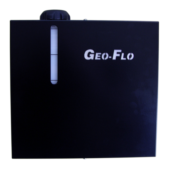
| Installation, Operating, and Maintenance Manual Rev. 27APR2017 Appendix A - Adjusting Pressure Switch Setting The factory selected pressure switch setting* of 25 psig +/- 3 psig should be appropriate for most geothermal and hydronic system applications regardless of how the system is plumbed and wired. However, the pressure switch setting may adjusted to fit the specific installation. - Page 11 Manual Updates Table Date Description of Changes Pages 27APR2017 Updated max. pressure setting and range (ON: 25 psig; OFF: 35 Various psig; +/- 3 psig) Added additional troubleshooting tips Added Appendix A for adjusting pressure switch 23JUL2015 Updated picture to new black cabinet Cover, page 1 Updated parts listed (new check valve assembly) Updated Figure 1 to include to flex hose with check valve...
- Page 12 888-477-8829 Geo-Flo Products Corporation is continually working to improve its products. As a result, the design and specifications of products in this document may change without notice and may not be as described herein. For the most up-to-date information, please visit our website, or contact our customer service department at jmoan@geo-flo.com.
Need help?
Do you have a question about the Geo-Booster 3619 and is the answer not in the manual?
Questions and answers