Advertisement
Quick Links
Advertisement

Summary of Contents for MERLO CDC
- Page 1 MERLO UK CDC Quick Guide THE DYNAMIC LOAD CONTROL SYSTEM...
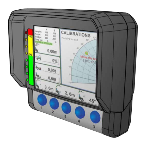
- Page 3 OPERATING INSTRUCTIONS (SW Version 2.3) NOMENCLATURE OF DISPLAY A] Screen Graphic LED bar Keyboard...
- Page 4 OPERATING INSTRUCTIONS (SW Version 2.3) SWITCH ON AND MAIN SCREEN Turn the ignition key to the ‘R’ position. The system displays a screen with the MERLO symbol for 3 seconds and then automatically shifts to the main screen.
- Page 5 OPERATING INSTRUCTIONS (SW Version 2.3) The main screen shows the following information: REF. DESCRIPTION Longitudinal stability limit (percentage) Maximum load liftable from the spot the telescopic boom is in (shown by the green/amber/red coloured indicator (9) on the dynamic load chart) depending on the attachment Load lifted from the spot the telescopic boom is in (shown by the green/amber/red coloured indicator (9) on the dynamic load chart) Load height from the ground (shown in metres)
- Page 6 OPERATING INSTRUCTIONS (SW Version 2.3) ACTIVATION OF THE GRAPHIC BAR FOR CONTROL SELECTION Display of the load control system is equipped with a floating bar which shows control buttons P1, P2, P3, P4 and P5. The activation of this floating bar depends on the weighing mode selected by the operator: In the ‘AUTO WEIGHING’...
- Page 7 OPERATING INSTRUCTIONS (SW Version 2.3) DISPLAY SETUP (BUTTON P1) Carry out the following operations to adjust the brightness of display (both in a daytime and in a night mode) and the volume of the loudspeaker: activate the menu bar press button (P1): a screen appears where you can adjust both display brightness and volume press button (P2) to select the graphic bar correspon- ding to the setting you need to modify (in this order:...
- Page 8 OPERATING INSTRUCTIONS (SW Version 2.3) The system informs the operator about the selected mode by displaying either window (daytime mode) or (night mode) in the middle of display. daytime mode night mode WEIGHING SCREEN (BUTTON P5) From the main screen, activate the menu bar, then press button (P5) to enter the weighing screen, where the following information is shown:...
- Page 9 OPERATING INSTRUCTIONS (SW Version 2.3) REF. DESCRIPTION Net weight lifted by the attachment installed on the carriage (expressed in tonnes) Table showing the latest 20 weighings stored in the system, including the total weight Deletion of all weighings stored in the system. The total is set back to zero. Attachment tare Manual weighing Selection of the weighing mode: either automatic or manual...
- Page 10 OPERATING INSTRUCTIONS (SW Version 2.3) 2) RESET (C) The reset control allows you to delete all the weighing values stored in table 'B'. When all the partial weighing values are deleted, the overall weighing value is set back to zero too. To carry out the reset procedure you need to scroll the weighing screen with button (P2) until you select 'RESET'.
- Page 11 OPERATING INSTRUCTIONS (SW Version 2.3) 3) TARE (D) This control allows you to tare the weighing system. In this way field (A) will subsequently show only the weight of the load being lifted, without the weight of the attachment. To carry out the taring procedure you need to scroll the weighing screen with button (P2) until you select ‘TARE’. Then press (P3) to confirm.
- Page 12 OPERATING INSTRUCTIONS (SW Version 2.3) 4) MANUAL WEIGHING (E) Use this control to manually weigh the load being lifted on the attachment. The data measured by the system are shown in table 'B', from cell number 1 to cell number 20. After 20 weighings all the values scroll up, and the next values are displayed at the bottom of the table.
- Page 13 OPERATING INSTRUCTIONS (SW Version 2.3) 5) WEIGHING MODES (F) Use this control to set the weighing mode: 1) MANUAL 2) AUTOMATIC Is the manual mode selected, symbol 'X' appears with the 'MAN WEIGHING' inscription next to it. Is the automatic mode selected, the 'Y' symbol appears with the 'AUTO WEIGHING' inscription next to it.
- Page 14 OPERATING INSTRUCTIONS (SW Version 2.3) To confirm that the system was correctly set in the automatic mode, field (14) on the main screen shows the 'Y' symbol and the value you selected for the boom lift angle (in degrees). In this way, whenever the telescopic boom is lifted beyond the angle you selected, the system carries out an automatic weighing (emitting the corresponding tone), and stores the value in table 'B'.
- Page 15 OPERATING INSTRUCTIONS (SW Version 2.3) 6) WEIGHING MODIFICATION (G) Should you need to either modify or delete one or several weighings stored in table 'B' you can do that using the modi- fication function available on the WEIGHING SCREEN. Scroll the weighing screen with button (P2) until you select 'EDIT DATA', then press button (P3) to confirm.
- Page 16 OPERATING INSTRUCTIONS (SW Version 2.3) SWITCH FOR THE SELECTION OF THE TYPE OF ATTACHMENT INSTALLED ON THE CARRIAGE (D) Your machine is equipped with a 4-position selector switch (D) which allows the operator to select -either manually or automatically- the type of attachment installed on the car- riage, so as to determine the load capacity chart suitable for the machine/attachment combination.
- Page 17 OPERATING INSTRUCTIONS (SW Version 2.3) For the operation modes of selector (D) please refer to the following instructions: SELF-IDENTIFICATION OF AN ATTACHMENT (selector (D) in the AUTO position) When an attachment equipped with a self-identification sensor is installed on the carriage, you need to shift se- lector (D) to the "AUTO"...
- Page 18 OPERATING INSTRUCTIONS (SW Version 2.3) If the self-identification system works correctly but there is no graphic representation of the attachment installed on the carriage, the machine signals it by showing the corre- sponding symbol in field (12) of display (A) in the cab. MANUAL SELECTION OF AN ATTACHMENT (selector (D) in the 0.5/0.6 or 1.5 or 4 position) When either an attachment not equipped with a self-identification sensor is installed on the carriage or an error/mal- functioning occurs in the system, you need to manually select the category the attachment belongs to by operating...
- Page 19 OPERATING INSTRUCTIONS (SW Version 2.3) Field (12) shows the graphic representation of the position of selector (D) If the selector (D) is turned to the AUTO position and: an attachment not equipped with a self-identification sensor is installed on the carriage, or an error/malfunctioning occurs in the system The system automatically activates the work chart corre- sponding to the “C”...
- Page 20 OPERATING INSTRUCTIONS (SW Version 2.3) SYMBOL SHOWN IN DESCRIPTION FIELD (12) The attachment installed on your machine is either not equipped with a self-identifica- tion sensor, or it was not automatically identified by the system due to a system failure or malfunctioning.
- Page 21 OPERATING INSTRUCTIONS (SW Version 2.3) POSIZIONE SELETTORE SYMBOL SHOWN IN SOLO PER DESCRIPTION FIELD (12) ATTREZZATURA SENZA SENSORE FLY JIB (A1210 - A1210A) FLY JIB WITH A WINCH (A1215 - A1310 - A1310A) attachment installed on the machine was correctly identified by the system.
- Page 22 OPERATING INSTRUCTIONS (SW Version 2.3) POSIZIONE SELETTORE SYMBOL SHOWN IN SOLO PER DESCRIPTION FIELD (12) ATTREZZATURA SENZA SENSORE The PUSHING BLADE attachment installed on the machine was correctly identified by the system. The WHEEL MANIPULATOR attachment installed on the ma- chine was correctly identified by the system.
- Page 23 OPERATING INSTRUCTIONS (SW Version 2.3) POSIZIONE SELETTORE SYMBOL SHOWN IN SOLO PER DESCRIPTION FIELD (12) ATTREZZATURA SENZA SENSORE The SLEWING HOIST attachment installed on the machine was correctly identified by the system. The COUNTER-CARRIAGE MOUNTED HOIST attachment in- stalled on the machine was correctly identified by the system. FIXED PLATFORM SLEWING PLATFORM VARIABLE-WIDTH SLEWING PLATFORM...
- Page 24 OPERATING INSTRUCTIONS (SW Version 2.3) POSIZIONE SELETTORE SYMBOL SHOWN IN SOLO PER DESCRIPTION FIELD (12) ATTREZZATURA SENZA SENSORE The TUNNEL RIB HANDLER attachment installed on the ma- chine was correctly identified by the system. The PANEL HANDLING PLATFORM attachment installed on the machine was correctly identified by the system.
- Page 25 OPERATING INSTRUCTIONS (SW Version 2.3) FRONT OVERTURN PREVENTION SYSTEM The front overturn prevention system steps in when the machine is close to its longitudinal stability limit, and locks all aggravating movements. While handling a load, the system automatically detects and processes the position of the load being lifted on the car- riage, as well as the percentage stability of your machine.
- Page 26 OPERATING INSTRUCTIONS (SW Version 2.3) • value beyond 125% the machine has reached its longitudinal stability li- mit, and all aggravating movements are locked as a consequence warning light on the dashboard is on, and the audible alarm in the cab is set off load chart indicator (9) is red-coloured graphic bar (B) has a red LED on As we saw before, the dynamic load control system steps in when the overturning prevention system percentage is...
- Page 27 OPERATING INSTRUCTIONS (SW Version 2.3) OPERATING MODE SELECTOR FOR THE OPERATION OF THE MACHINE EITHER AS A TELEHANDLER OR AS A FRONT LOADER (If present) Selector features 2 operating positions: position "0": use this function for load handling. position "1": use this function when using agricultural attachments (bucket, multi-purpose bucket, manure forks, etc.).
- Page 28 OPERATING INSTRUCTIONS (SW Version 2.3) If the load being lifted on the carriage (shown by coloured circle "X" on the display in the cab) is within working area "A" highlighted in yellow, the stability control system of the machine steps in as follows: warning light on instrument panel switches on the audible alarm in the cab is set off no movement of the telescopic boom is locked...
- Page 29 OPERATING INSTRUCTIONS (SW Version 2.3) ACTIVATION OF TEMPORARY BYPASS SWITCH (If present) A Hold-to-Run Button on the steering column allows the operator to temporarily disable the lockout function, for a maximum period of 10 seconds. This device is an alternative to the Operating Mode Selector rotated to "C" position, which has the same effect. The operation of button) depends on the position of selector, which allows the machine to be operated as either a telehandler or a front loader.
- Page 30 OPERATING INSTRUCTIONS (SW Version 1.0) WORKING MODE SELECTOR Emergency movements (control with a spring return to the "B" position). The "C" position of selector is no longer equipped with a timer as previous version. This function is shown on display in the cab with an in- formation window "X"...
Need help?
Do you have a question about the CDC and is the answer not in the manual?
Questions and answers